
Are you a homeowner researching the benefits of an underground living space? Read our complete guide to ICF Basements here.
This guide details the step-by-step process for contractors and installers constructing a below-grade foundation using BuildBlock Insulating Concrete Forms (ICF), from excavation through final waterproofing.

Footings must be poured on undisturbed soil or properly compacted fill, sized according to the engineer’s specifications.
First Course Setting Methods:
Dry-Set (Glue-Down): Pour and cure the footing, then adhere the first course of ICF blocks to the hardened concrete using foam adhesive. (Recommended for basements).
Wet-Set: Press the first course of blocks directly into the freshly poured concrete footing before it cures.
Mono-Pour: Use special brackets to suspend the fully built ICF wall above the footing trench and pour the footing and walls simultaneously. (Advanced installers only).
Rebar Dowels: Regardless of the method, rebar dowels must be set in the footing to receive the vertical rebar. For basements, spacing typically varies from 12-24” on center.

First Two Courses: Stack, level, and secure the first two courses. Ensure they are perfectly level through shimming and trimming.
Running Bond: Stack forms in a running bond pattern, alternating the long and short edges of the reversible corners so vertical joints do not align.
Horizontal Rebar: Place horizontal rebar in the web saddles every 6 inches. Crucial: Below grade, offset the horizontal rebar one groove toward the interior (the tension side of the wall).
Vertical Rebar: Slip vertical rebar down through the cavities to create a lap splice with the footing dowels (typically a minimum 40 bar diameter lap).
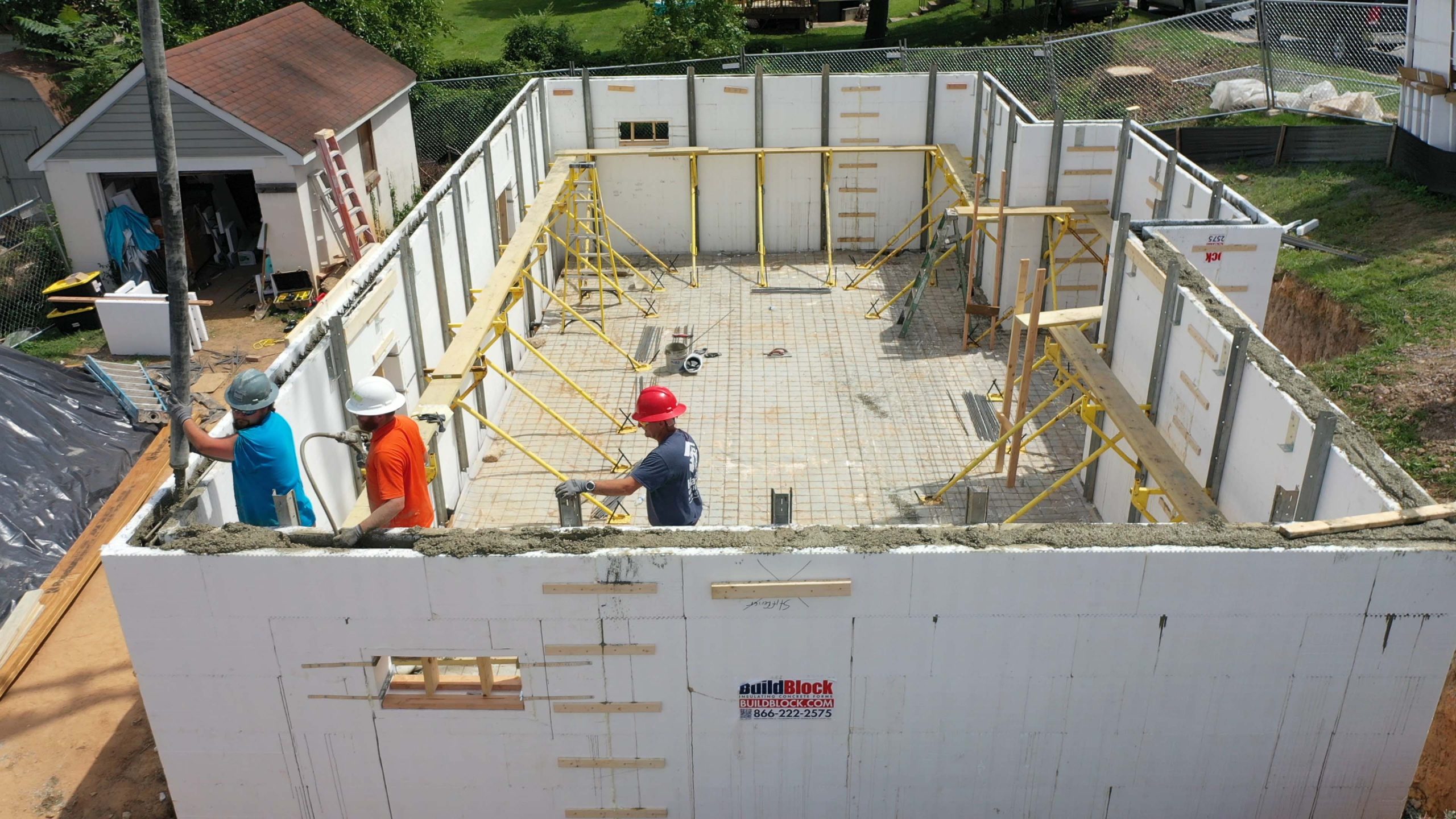
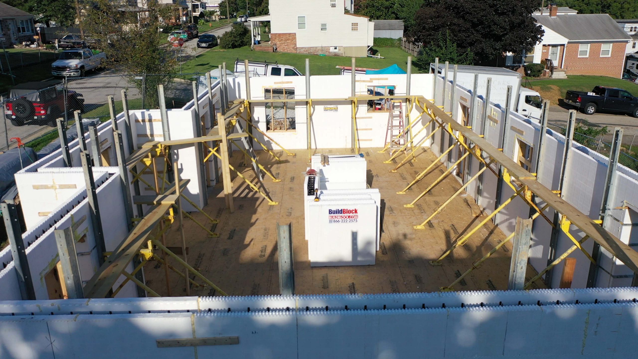
Bracing: When the wall reaches 4-5 courses, install a professional alignment system (like BuildBrace) on the inside face to keep the wall straight and plumb during the pour.
Penetrations: Cut through the foam and insert PVC sleeves slightly larger than needed for plumbing, electrical, and HVAC. Seal around the perimeter.
Openings: Frame basement egress windows and doors using BuildBuck or treated lumber bucks. Brace openings horizontally and vertically before the pour.

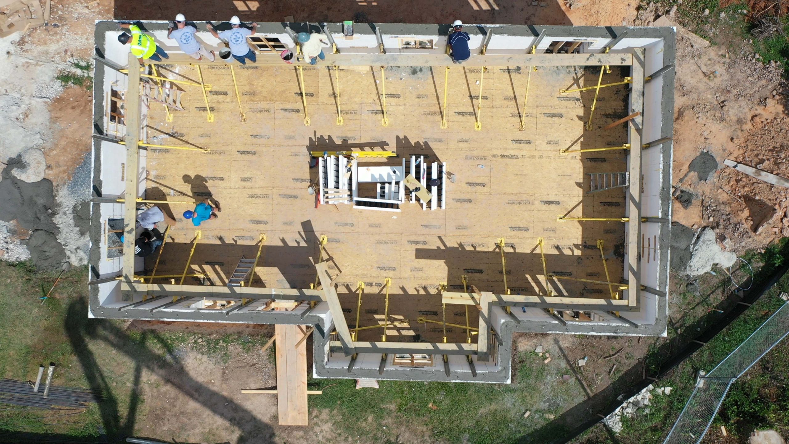
BuildDeck: Integrate stay-in-place ICF floor decking (top-mount or side-mount).
Joist Hangers: Embed Burmon or Simpson ICF hangers directly into the concrete core prior to the pour.
Suspended Concrete (SuperFloor): Cast-in-place or precast panels bearing directly on the concrete core.
Traditional Wood/TJI: Embed anchor bolts in the top course to secure a pressure-treated sill plate.

Insulated Concrete Form Deck Systems (BuildDeck)
BuildDeck is a stay-in-place ICF floor and roof decking system that integrates directly with the ICF wall system. When using BuildDeck, the installer first stacks the wall to the intended top-of-floor height, then decides whether to top-mount or side-mount the deck system to the wall — a decision that affects how the interior foam panel of the wall is cut. In a top-mount installation, the deck sits on top of the wall’s concrete core, creating a monolithic connection when the deck and wall are poured together or in close sequence. In a side-mount configuration, the deck bears against the side of the wall and the interior foam panel is trimmed to accommodate it. BuildDeck is available in 8″, 10″, and 12″+ depths, and like wall ICFs, it uses EPS foam forms that remain in place as permanent insulation. The thickness of the floor system is dictated by the distance it is required to span. The result is a fully insulated, reinforced concrete floor/ceiling assembly that ties structurally into the ICF wall — ideal for multi-story all-concrete construction where thermal continuity and strength are the priorities.

Joist Hanger and Ledger Connector Systems (Burmon, Simpson)
For wood-framed or TJI (engineered I-joist) floor systems, the connection to the insulated concrete form (ICF) wall is typically made through steel joist hangers or ledger connectors embedded in the concrete cast-in-place during the ICF pour. Burmon ICF hangers are purpose-built for this application — they are designed to be installed into the ICF wall before the pour by fastening through the foam directly into concrete core, with the joist seat extending to the interior to carry wood or TJI joists. Simpson Strong-Tie also produces ICF-compatible hangers and ledger connectors as well. Burmon and Simpson ICF joist hangers are set into the ICF form at the correct height and spacing prior to the pour. The back plate or embedment portion of the hanger sits within the foam cavity and becomes encased in concrete, while the joist seat protrudes through or beyond the interior foam face. This creates a direct steel-to-concrete load path for a structural connection. The foam is typically notched or the hanger is designed to penetrate through the interior panel so the seat is accessible after the wall is poured and cured.
The key advantage of these systems is that they allow a conventional wood floor system to bear on an ICF wall with or without a continuous ledger board or a concrete ledge, preserving the wall’s thermal envelope. Load tables from the hanger manufacturer must be consulted to confirm capacity at the required joist spacing and span.
Cast-in-Place Suspended Concrete Floor Systems (Super Floor)
Super Floor and similar cast-in-place or precast suspended concrete panel systems offer a high-strength, low-deflection floor option that bears directly on the insulated concrete form (ICF) wall’s concrete core. These systems typically consist of a proprietary pour-in-place panel system or precast concrete planks that span between walls on top of steel joists. The floor bears on the top of the ICF wall, resting on the concrete core rather than on the foam, so a properly leveled and flat top of wall is critical. Rebar stub-outs from the ICF wall can be tied into the floor system’s reinforcing to create a moment connection if the system requires it. This is a particularly popular approach in commercial ICF construction and basement-to-first-floor transitions where a concrete floor over the basement is desired or required based on spans or design.
Traditional Wood and TJI Floor Systems Bearing on the Wall
The simplest and most common approach in residential insulated concrete form (ICF) construction is to bear a conventional wood or TJI floor system directly on the top of the ICF wall’s concrete core, using a pressure-treated sill plate anchored with cast-in bolts. Anchor bolts are set into the top course of the ICF wall before the concrete pour, positioned to align with the sill plate layout, with bearing points carefully coordinated with the structural loads above. The sill plate is then bolted down after the pour, and standard joist hangers or face-mount hardware connects joists to a rim board sitting on the plate.
This method is familiar to most framers, requires no specialty products, and accommodates standard wood, LVL, or TJI joist systems. The main consideration is ensuring the sill plate sits on concrete — not on foam — and that anchor bolt spacing meets code requirements for the loads being transferred.
In all cases, backfilling of basement walls must not occur until the floor system is in place to brace the wall tops against lateral soil pressure. In short, the choice of floor system comes down to project type, story height, structural loads, and whether full concrete construction or a hybrid wood/concrete approach best fits the design. All methods are well-supported in BuildBlock’s ecosystem of products and accessories.

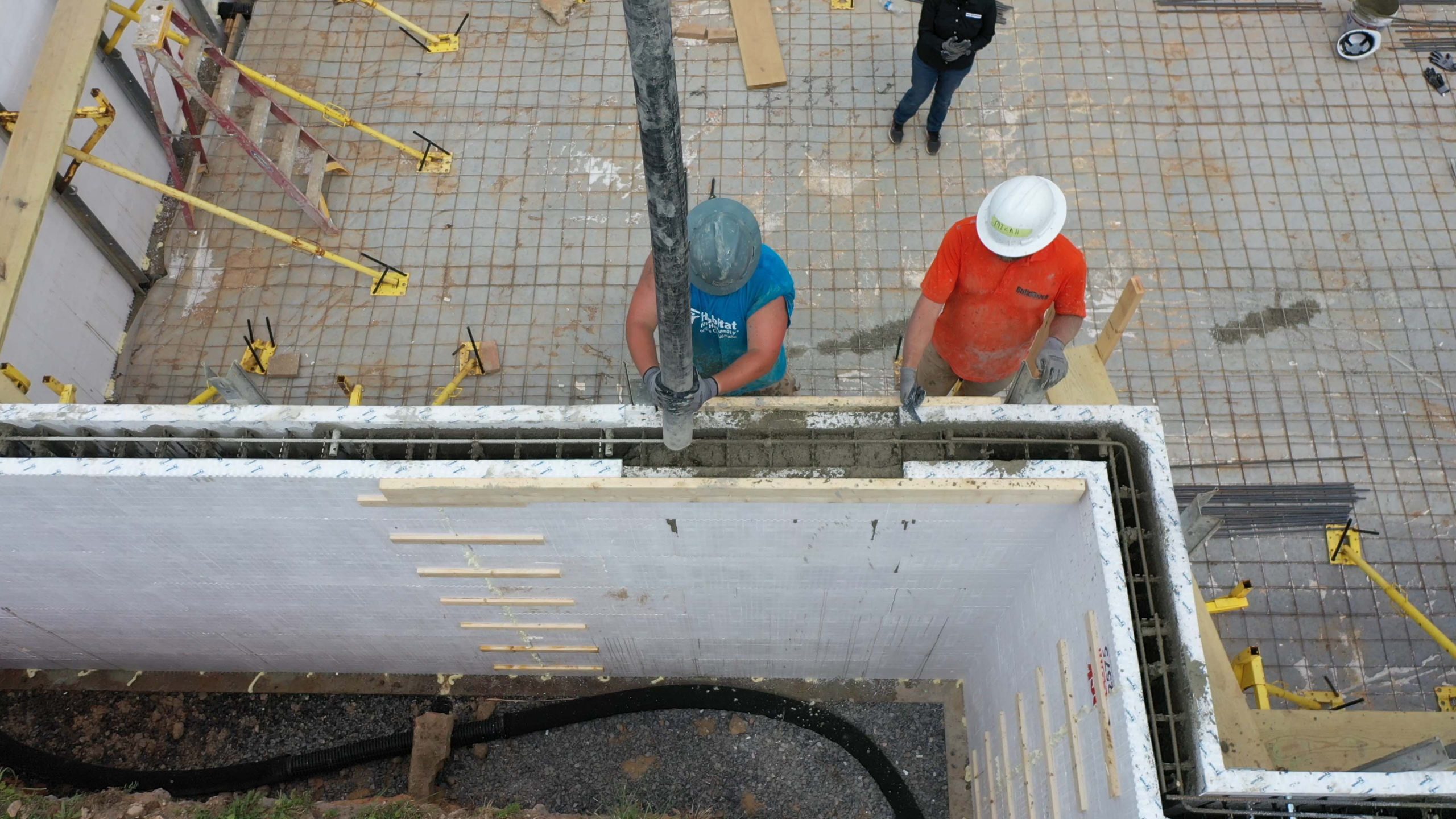
Installer using a pencil vibrator to consolidate the concrete. Mix: Typically a 3,000 PSI mix using 3/8-inch aggregate with a 5-to-7-inch slump. Always slump test.
Placement: Use a boom or trailer pump. Place in lifts of no more than 4 feet at a time, moving continuously around the perimeter.
Corners: Do not pour concrete directly into a corner. Let it drop straight down near the corner and flow naturally.
Consolidation: Use an internal pencil vibrator after each lift (fast in, slow out) to remove entrained air.
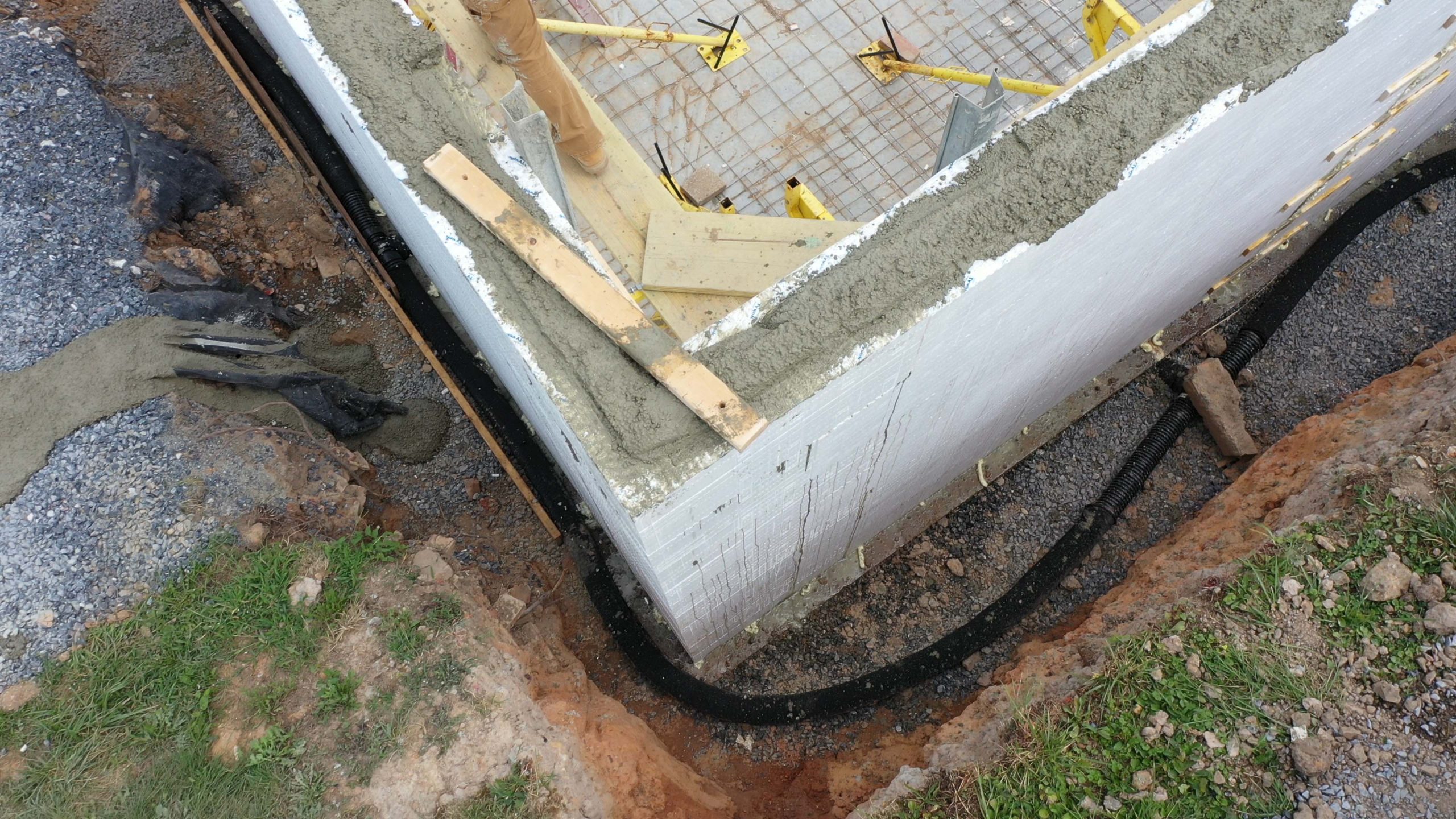
Primary Membrane: Apply a self-adhesive peel-and-stick membrane (e.g., Poly Wall Home Stretch). Apply vertically with 3-inch overlapping seams, extending onto the footing.
Drainage Plane: Install an air gap/dimple membrane (e.g., DMX-AG) over the peel-and-stick layer. Do not puncture the primary membrane.
Additives (Optional): Crystalline waterproofing additives (e.g., Penetron, Xypex) can be added to the concrete mix for additional internal protection.
Place fine gravel around the footing drain (minimum 12 inches high), topped with silt cloth.
Crucial: Do not backfill until the floor system above is installed to brace the walls.
Place backfill in 2-foot lifts and compact with small machinery. Ensure final grade slopes away from the foundation.
Utilities: Cut chases directly into the foam face for electrical wiring (minimum 2 inches deep) and secure with spray foam.
Drywall: Attach drywall directly to the ICF web ties using coarse thread screws. The foam provides continuous insulation, requiring no additional framing or batts.
Building a basement with insulated concrete forms is a sequential, detail-driven process. The quality of every subsequent step depends on the precision of the one before it — a square excavation produces a square footing, a level first course produces a plumb wall, a properly braced wall survives the concrete pour, and a carefully waterproofed and backfilled exterior keeps the basement dry for the life of the structure. Done right, the result is a basement that is substantially stronger than a conventional poured concrete or masonry block foundation, better insulated than any above-grade wood-frame wall, and highly resistant to moisture, fire, and extreme weather events.
Building a basement foundation with insulated concrete forms (ICF) is one of the most durable, energy-efficient, and cost-effective approaches available. The resulting walls combine a reinforced concrete core with continuous expanded polystyrene (EPS) foam insulation on both sides — creating a structure that is stronger, quieter, and better insulated than a conventionally poured basement.