How to Build: Footings (to Applicable Codes)
Footings distribute loads from the structure to the ground and in most cases are either specified by an engineer or architect. They are regulated, standardized and inspected by local building code officials. They vary dramatically across the country. If you are planning to build in an area that has no restrictions regarding footing size and re-enforcing standards, BuildBlock recommends you seek a local structural engineer to specify your load requirements and footing sizings. This step will avoid costly structural problems and assure your structure sits on a proper foundation. Keep in mind there are a variety of factors that play into the design of a foundation. Most building professionals seek the services of a structural engineer.
There are a variety of factors that play into the design of a foundation:
- Soil Bearing Capacity and Soil Type
- Structure Loading
- Code Compliance
- Proper Reinforcing
- Frost Lines
- Moisture Control
BuildBlock highly recommends the consultation of a structural engineer familiar with your region’s soil load bearing capacities for accurate footing designs. Because different engineers recommend various footing thicknesses and widths, we are providing two footing charts for your convenience.
Above Grade | Load Bearing Value of Soil (psf) 1-Story
Profile | Rt. (plf) | 1,000 | 1,500 | 2,000 | 2,500 | 3,000 |
|---|---|---|---|---|---|---|
BB-400 | 1,590 | w=20" h=10" | w=20” h=10” | w=16” h=8” | w=16” h=8” | w=16” h=8” |
BB-600 | 1,590 | w=20” h=10” | w=20” h=10” | w=13” h=8” | w=16” h=8” | w=16” h=8” |
BB-800 | 1,790 | w=22” h=12” | w=22” h=12” | w=18” h=8” | w=16” h=8” | w=16” h=8” |
Above Grade | Load Bearing Value of Soil (psf) 2-Story
Profile | Rt. (plf) | 1,000 | 1,500 | 2,000 | 2,500 | 3,000 |
|---|---|---|---|---|---|---|
BB-400 | 3,130 | w=38” h=12” | w=28” h=12” | w=20” h=10” | w=16” h=8” | w=16” h=8” |
BB-600 | 3,130 | w=38” h=12” | w=28” h=12” | w=20” h=10” | w=16” h=8” | w=16” h=8” |
BB-800 | 3,550 | w=43” h=13” | w=32” h=12” | w=24” h=12” | w=19” h=10” | w=16” h=9” |
Below Grade | Load Bearing Value of Soil (psf) 1-Story
Profile | Rt. (plf) | 1,000 | 1,500 | 2,000 | 2,500 | 3,000 |
|---|---|---|---|---|---|---|
BB-400 | 3,130 | w=38” h=12” | w=28” h=12” | w=20” h=10” | w=16” h=8” | w=16” h=8” |
BB-600 | 3,130 | w=38” h=12” | w=28” h=12” | w=20” h=10” | w=16” h=8” | w=16” h=8” |
BB-800 | 3,550 | w=43” h=13” | w=32” h=12” | w=24” h=12” | w=19” h=10” | w=14” h=9” |
Below Grade | Load Bearing Value of Soil (psf) 2-Story
Profile | Rt. (plf) | 1,000 | 1,500 | 2,000 | 2,500 | 3,000 |
|---|---|---|---|---|---|---|
BB-400 | 4,670 | w=56” h=16” | w=36” h=14” | w=28” h=12” | w=23” h=11” | w=18” h=8” |
BB-600 | 4,670 | w=56” h=16” | w=36” h=14” | w=28” h=12” | w=23” h=11” | w=18” h=8” |
BB-800 | 5,310 | w=64” h=18” | w=43” h=15” | w=32” h=13” | w=26” h=12” | w=22” h=11” |
Note: BuildBlock Building Systems assumes no liability for foundation requirements. Every geography has different soil and seismic conditions. These charts are for reference only. This chart assumes 3,000 PSI Concrete. For walls larger than 8-inches and veneer walls, consult your engineer.
Prescriptive Method for Insulating Concrete Forms
in Residential Construction (Second Edition)
TABLE 3.1
MINIMUM WIDTH OF ICF AND CONCRETE FOOTINGS FOR ICF WALLS1,2,3 (inches)
Maximum Number of Stories (4) | Minimum Load-Bearing Value of Soil | ||||
|---|---|---|---|---|---|
- | 2,000 | 2,500 | 3,000 | 3,500 | 4,000 |
5.5-Inch Flat, 6-Inch Waffle-Grid, or 6-Inch Screen-Grid ICF Wall Thickness (5) | |||||
One-Story (6) | 15 | 12 | 10 | 9 | 8 |
Two-Story (6) | 20 | 16 | 13 | 12 | 10 |
7.5-Inch Flat or 8-Inch Waffle-Grid, or 8-Inch Screen-Grid ICF Wall Thickness (5) | |||||
One-Story (7) | 18 | 14 | 12 | 10 | 8 |
Two-Story (7) | 24 | 19 | 16 | 14 | 12 |
9.5-Inch Flat ICF Wall Thickness (5) | |||||
One-Story | 20 | 16 | 13 | 11 | 10 |
Two-Story | 27 | 22 | 18 | 15 | 14 |
For SI: 1 foot = 0.3048 m | 1 inch = 25.4 mm | 1 psf = 47.8804 Pa
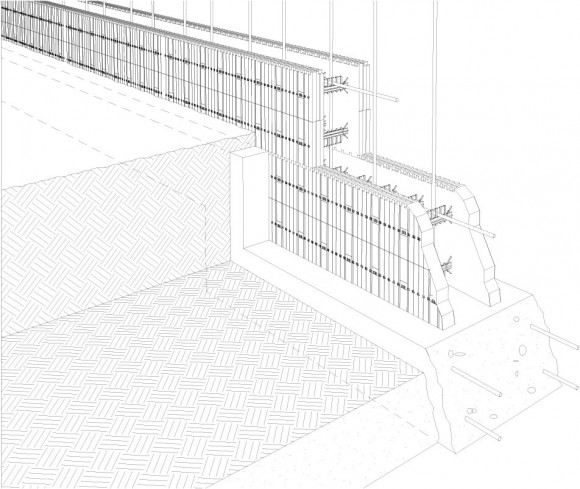
1 Minimum footing thickness shall be the greater of one-third of the footing width, 6 inches (152 mm), or 11 inches (279 mm) when a dowel is required in accordance with Section 6.0.
2 Footings shall have a width that allows for a nominal 2-inch (51-mm) projection from either face of the concrete in the wall to the edge of the footing.
3 Table values are based on 32 ft (9.8 m) building width (floor and roof clear span).
4 Basement walls shall not be considered as a story in determining footing widths.
5 Actual thickness is shown for flat walls while nominal thickness is given for waffle- and screen-grid walls. Refer to Section 2.0 for actual waffle/screen-grid thickness and dimensions.
6 Applicable also for 7.5-inch (191-mm) thick or 9.5-inch (241-mm) thick flat ICF foundation wall supporting 3.5-inch (88.9-mm) thick flat ICF stories.
7 Applicable also for 9.5-inch (241-mm) thick flat ICF foundation wall story supporting 5.5-inch (140-mm) thick flat ICF stories.
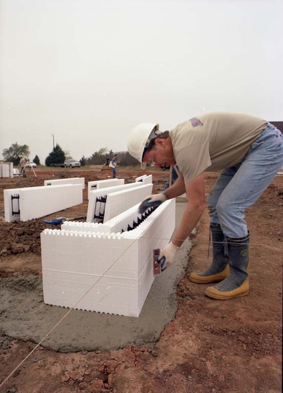
About Step Footings
One of the outstanding features of a BuildBlock form is its completely symmetrical web design. This means two identical half-height forms are produced when the form is cut in half horizontally.
This feature is particularly useful for step footings — an elevation change at the footing level. Plan your step footings in increments of one block height (16”) or half-block height (8”). This will ensure an easy transition and that your forms will line up properly. It also eliminates wasted forms.
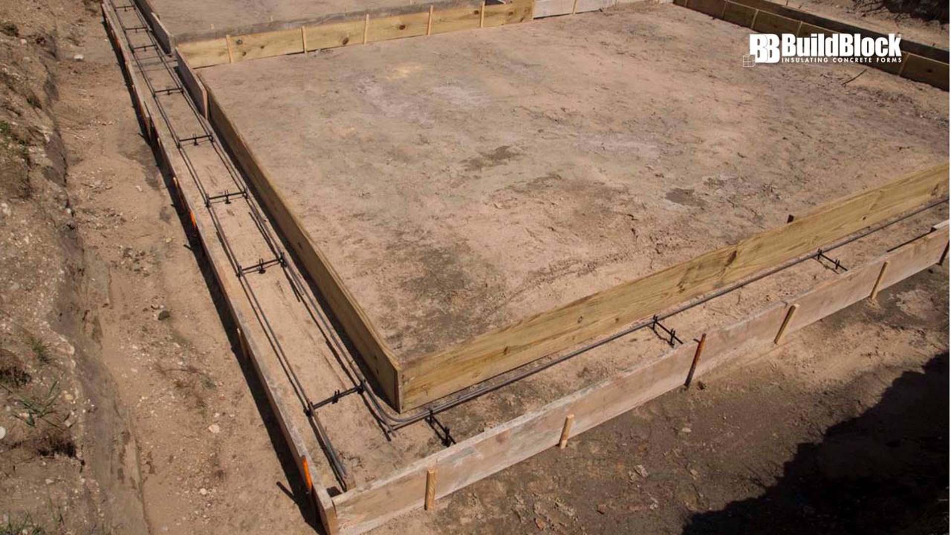
Pouring Footings
When your footings are dug and you place and tie your rebar, you are ready for a footing inspection (if applicable) and a call to your local concrete provider. Here are some things to keep in mind during this phase:
- First, if your footings are not accessible by a concrete truck you may have to use a trailer pump, conveyer truck or pump truck to fill the footing. (In which case you’ll have to order your mud as a pump mix.)
- Second, if pumping, the slump of the concrete will need to be a higher slump, or more flowable mix. The use of admixtures ( water reducers) is highly recommended to give flowability without weakening the concrete much, water alone to loosen concrete should be done sparingly.
- Third, when you pour your footings, take care that they are level and at correct elevation. A slightly rough surface is fine as long as it is level.
- Lastly, if form material is not used, to set concrete to pour height in earth dug footings install steel rod or wood stake pins every 3 to 4 feet with a level or laser level to your pour height. Pour and level concrete to these pins.
