How to Build an ICF Safe Room (FEMA P-361 Compliant)
How to Build an ICF Safe Room or Storm Shelter
Notice: BuildBlock uses the terms “safe room” and “storm shelter” separately. Safe room is used to refer to a residential application, while storm shelter is used when referring to a commercial application. The guides on this page refer to safe room construction for residential applications.
Building a Tornado ICF Safe Room: A Homeowner's Guide
A residential tornado safe room built with BuildBlock ICFs provides protection from tornadoes, hurricanes, and severe windstorms rated to FEMA P-361 and ICC 500 criteria. This guide walks you through what an ICF safe room is, why it works, what to expect during construction, and how to talk with your builder about the right design for your home.
What an ICF Safe Room Actually Is
An ICF safe room is a small, fully reinforced concrete room — usually 6 to 8 feet square or more — built inside the footprint of your house. The walls are constructed with BuildBlock forms: hollow EPS foam blocks that lock together like Lego, get filled with steel rebar and concrete, and produce a 6-inch-thick (or thicker) reinforced concrete wall sandwiched between two layers of continuous insulation.
The lid is the same idea, just horizontal: a reinforced concrete slab, either poured on plywood forms or built using the BuildBlock BuildDeck system, that ties directly into the walls.
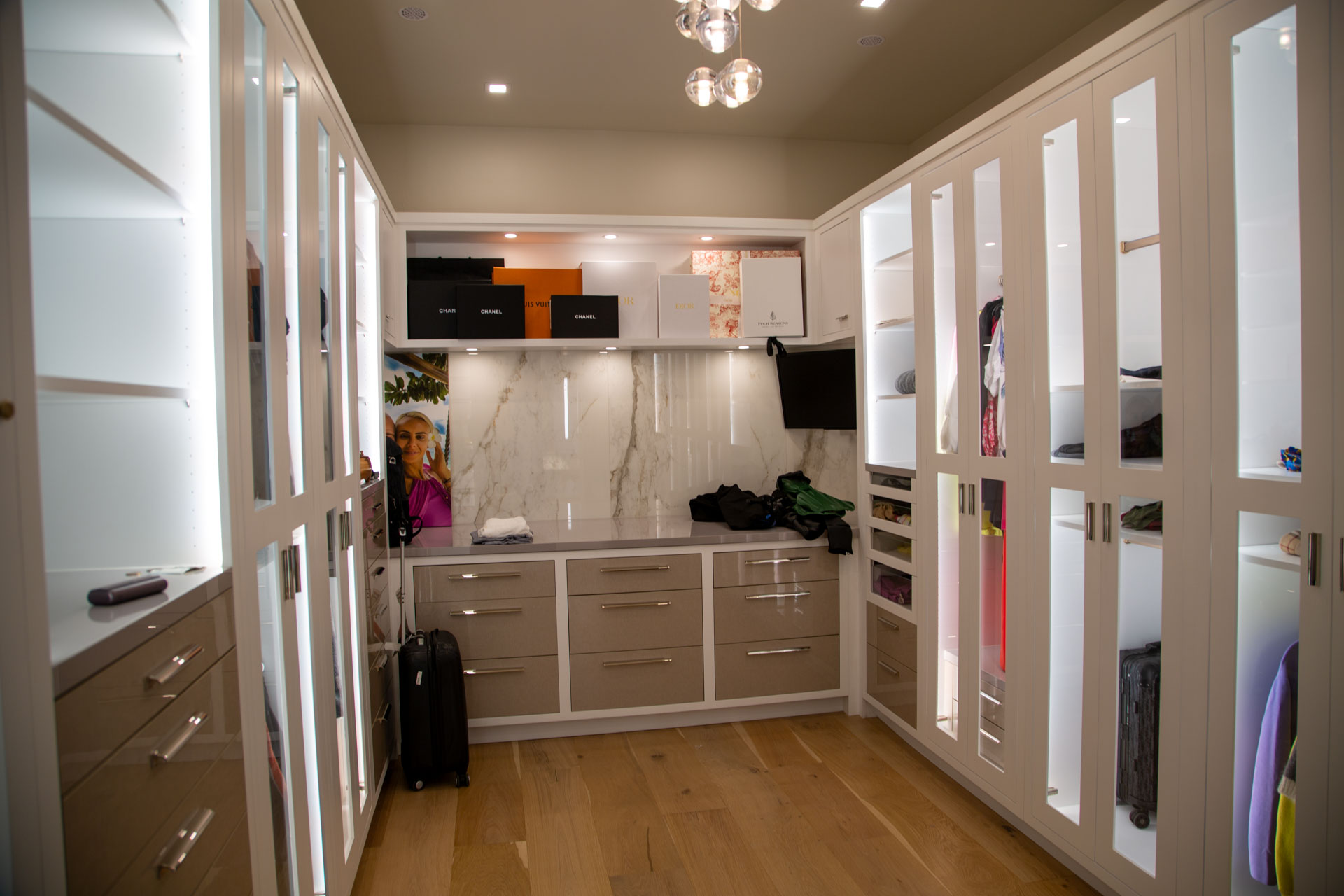
The result is essentially a small concrete bunker — but one that doubles every day as a master closet, bathroom, pantry, or office. Unlike a steel storm shelter parked in the corner of the garage, or one cut into the floor that can flood or become blocked by debris an ICF safe room is usable space every day.
Why Reinforced Concrete Performs in a Tornado
The protective performance of a safe room comes from three things: mass, reinforcement, and a tested door.
Mass absorbs energy. A 6-inch concrete wall weighs roughly 75 pounds per square foot. When a 15-pound 2×4 traveling 100 miles per hour hits that wall — the standard test missile for tornado shelters — the wall resists penetration and deflection with no structural damage.
Reinforcement holds the wall together when it does deflect. The rebar grid inside the concrete keeps the wall from cracking apart under wind pressure and uplift forces.
The door is the component most likely to be under-specified. The door, frame, hinges, and locks are the weakest point in any safe room, and the difference between a door that has been tested to FEMA 361 and ICC 500 standards and an ordinary residential door is enormous. More on that below.
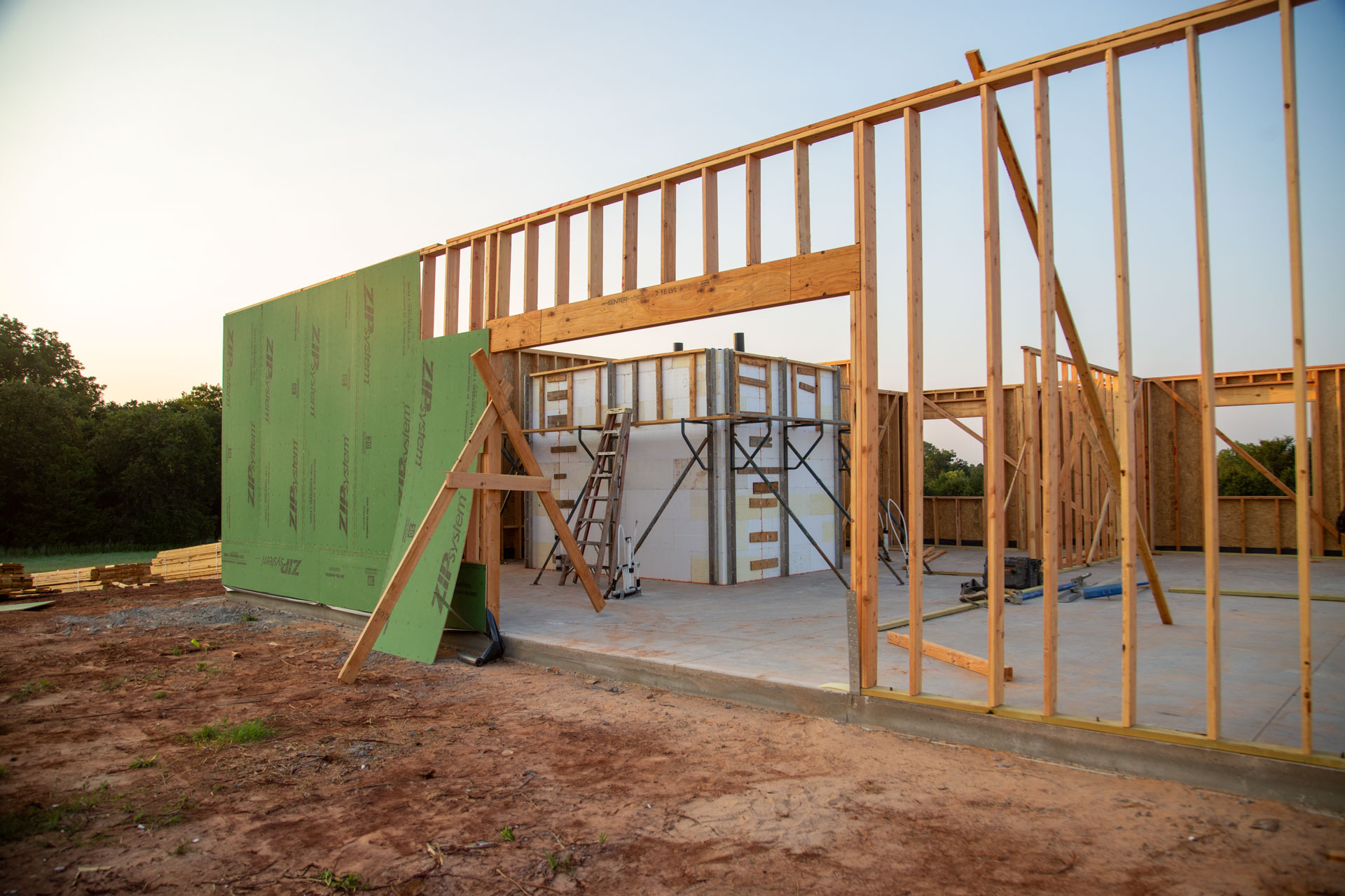
ICF safe room being built inside of a wood frame residential home.
BuildBlock's Pre-Engineered Safe Room Designs
The BuildBlock Engineering Manual includes a full chapter — Section 8.0 — devoted to safe room engineering. Within the design limits in that section, your builder can construct a pre-engineered safe room directly from the published tables: rebar schedule, wall thickness, BuildDeck lid specification, and ventilation sizing.
The pre-engineered envelope covers the vast majority of residential safe rooms: single-story or two-story applications, design wind speeds up to 250 mph 3-second gust, wall heights up to 20 feet unsupported, and standard family-sized rooms. For very tall walls, very high seismic zones, or coastal hurricane storm-surge locations, your engineer will produce a site-specific design instead.
The practical impact for you: a pre-engineered safe room is faster to permit, faster to build, and easier to price than a one-off custom design. Ask your builder whether your project falls within the pre-engineered envelope.
FEMA and ICFF Standards Referenced
You will hear three documents referenced when you start shopping for a safe room:
FEMA P-320 is the homeowner-facing guide — “Taking Shelter from the Storm.” It is written for you. FEMA P-320 is the appropriate starting document for homeowners.
FEMA P-361 is the technical standard for safe room design and construction. It is written for your builder and engineer.
ICC 500 is the structural standard FEMA P-361 references. It defines the wind speeds, missile impact tests, and pressure loads a safe room must withstand.
A safe room that “meets FEMA 361” or is “ICC 500 compliant” is one that has been designed to those standards as an entire assembly — walls, lid, door, anchorage, and ventilation. Each piece matters. A perfect wall paired with the wrong door is not a compliant safe room.
Rated vs. Non-Rated Doors
Here is a useful way to think about safe room doors: a rated door is tested and labeled as an assembly; a non-rated door may use similar materials but carries no test report and cannot be represented as FEMA-compliant.
A FEMA-rated, ICC 500-tested door assembly is the name brand. It has been tested with the ICC 500 impact missile, anchored into a wall matching the specified construction, and labeled with a manufacturer test report that you can hand to your insurance company. It typically costs $3,000 to $7,000.
A non-rated steel door is the generic. It may be built to similar weights and gauges, may anchor into the same concrete wall, and in many cases will perform similarly under stress — but it has not been tested as an assembly, has no label, and cannot be advertised as FEMA compliant. It typically costs $1,000 to $2,000.
Both choices are legitimate, depending on your goals. If you want a true FEMA-compliant safe room — for peace of mind, for resale, for a grant rebate, or for an insurance discount — you need the rated door. If you want a “safer room” that meaningfully improves your odds in a severe storm but stops short of the formal label, the non-rated door can be appropriate. Just be clear with yourself, your builder, and your insurance carrier about which one you are buying.
Disaster rated steel door frames for safe rooms.
Construction Sequence
A typical residential ICF safe room takes a four-person crew three to five working days from footing to ready-for-finishes.
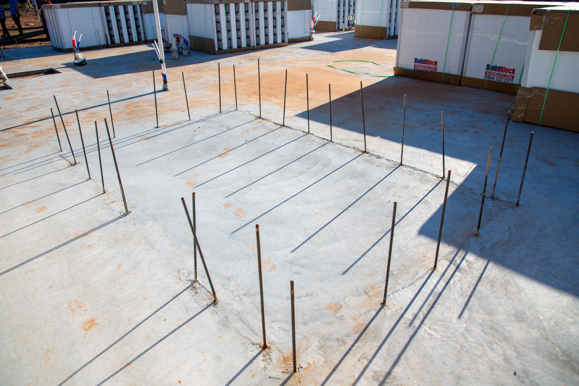
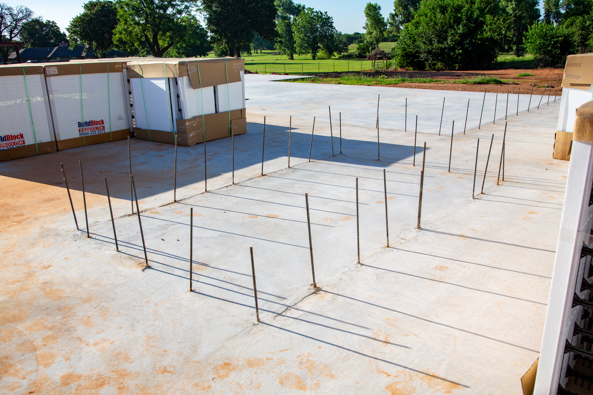
The footing is poured first, usually as part of the main house foundation. Steel dowels stick up out of the footing at regular spacing — these tie the walls to the foundation and are critical to the structural performance.
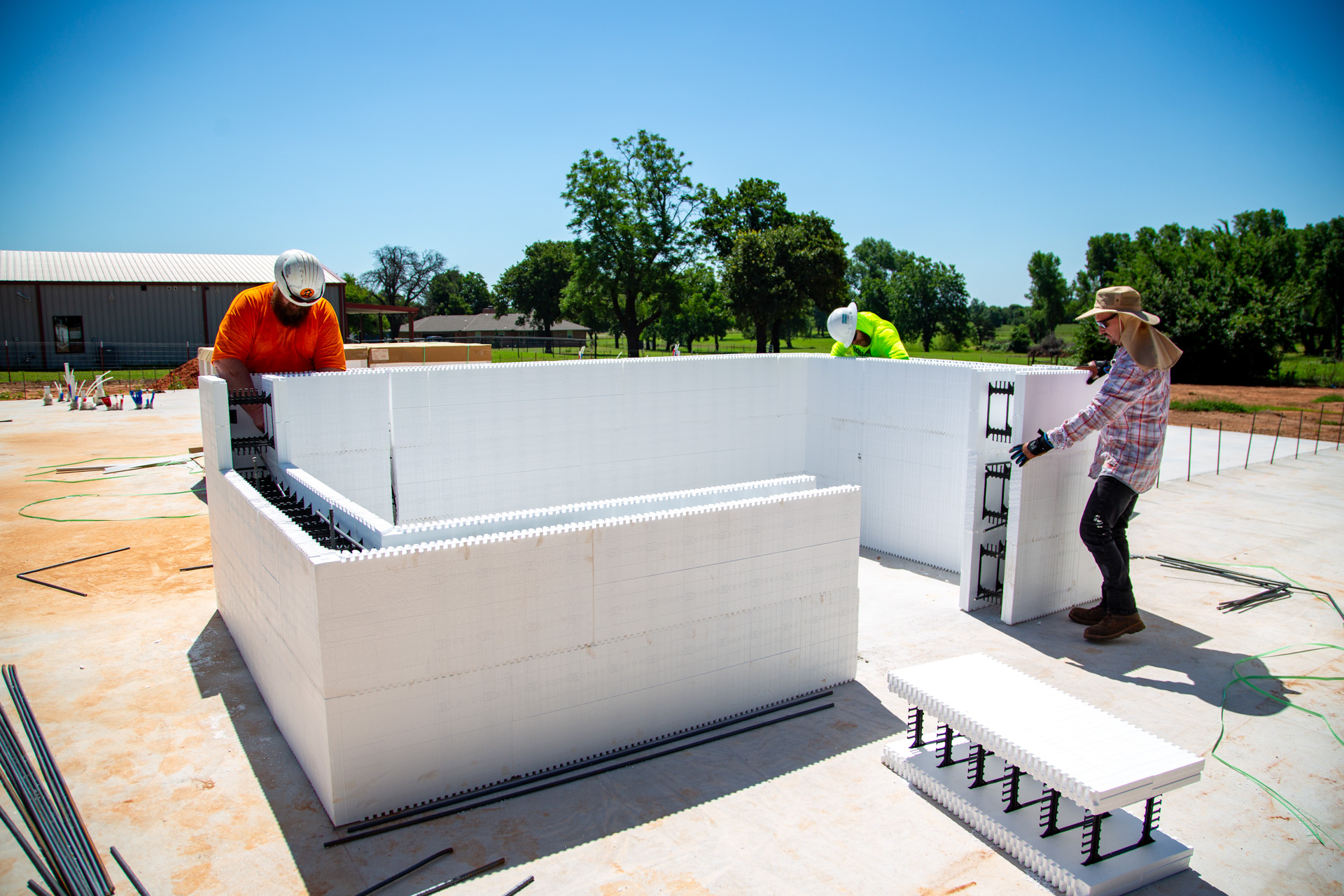
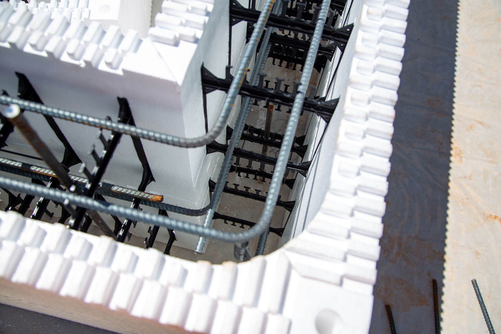
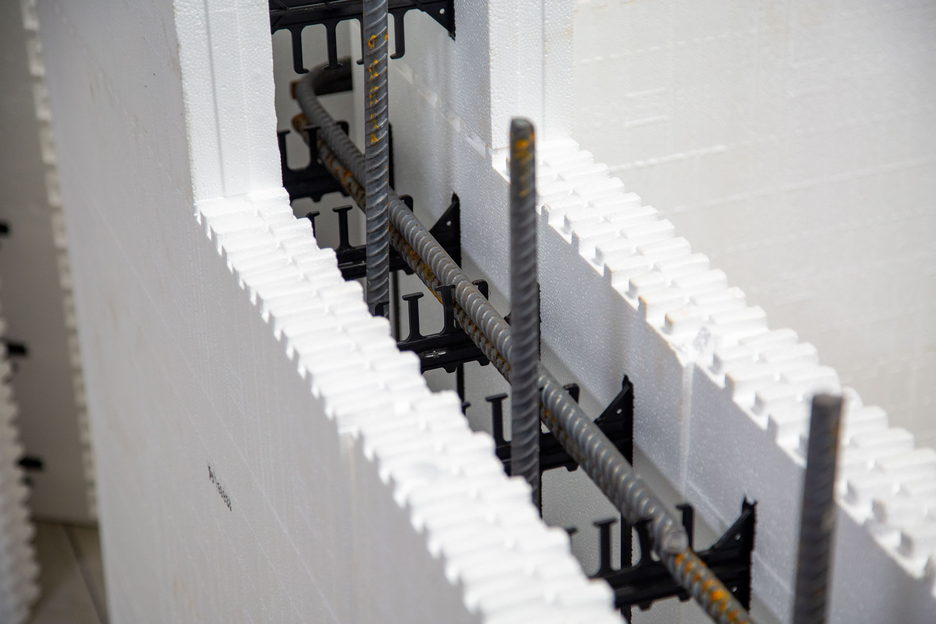
Walls are stacked dry, course by course, using BuildBlock forms. Horizontal rebar is placed every course and vertical rebar drops into the cores. A heavy steel door frame is installed and secured to ensure it doesn’t move during the pour. The whole assembly is braced with ICF bracing and the cap/lid is constructed reinforced and shored as needed.
The lid goes on next — either a poured concrete slab on plywood forms, or a BuildBlock BuildDeck system that integrates insulated joists directly into the wall. BuildDeck is the system specified in BuildBlock’s pre-engineered safe room tables and is the most efficient lid option for most residential applications.
Concrete is pumped into the walls in lifts, vibrated for consolidation, and allowed to cure. The bracing stays in place for 48 to 96 hours.
Mechanical rough-ins go in before drywall: a dedicated electrical circuit with battery backup, code-required smoke and CO detection, and impact-rated ventilation openings sized per the engineering manual (typically a pair of 2-inch vents with downward-facing elbows).
Drywall, paint, flooring, and trim finish the room exactly the way any other room in your house would be finished. When it is done, the only visible clue that it is a safe room is the door.
Vertical dowels in foundation for ICF safe room walls.
Stacking block around around the veritcal dowels.
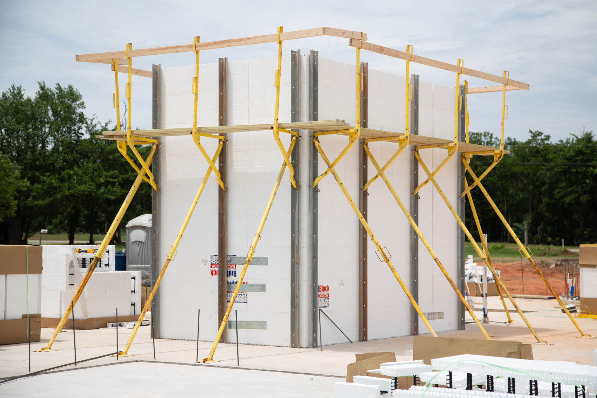
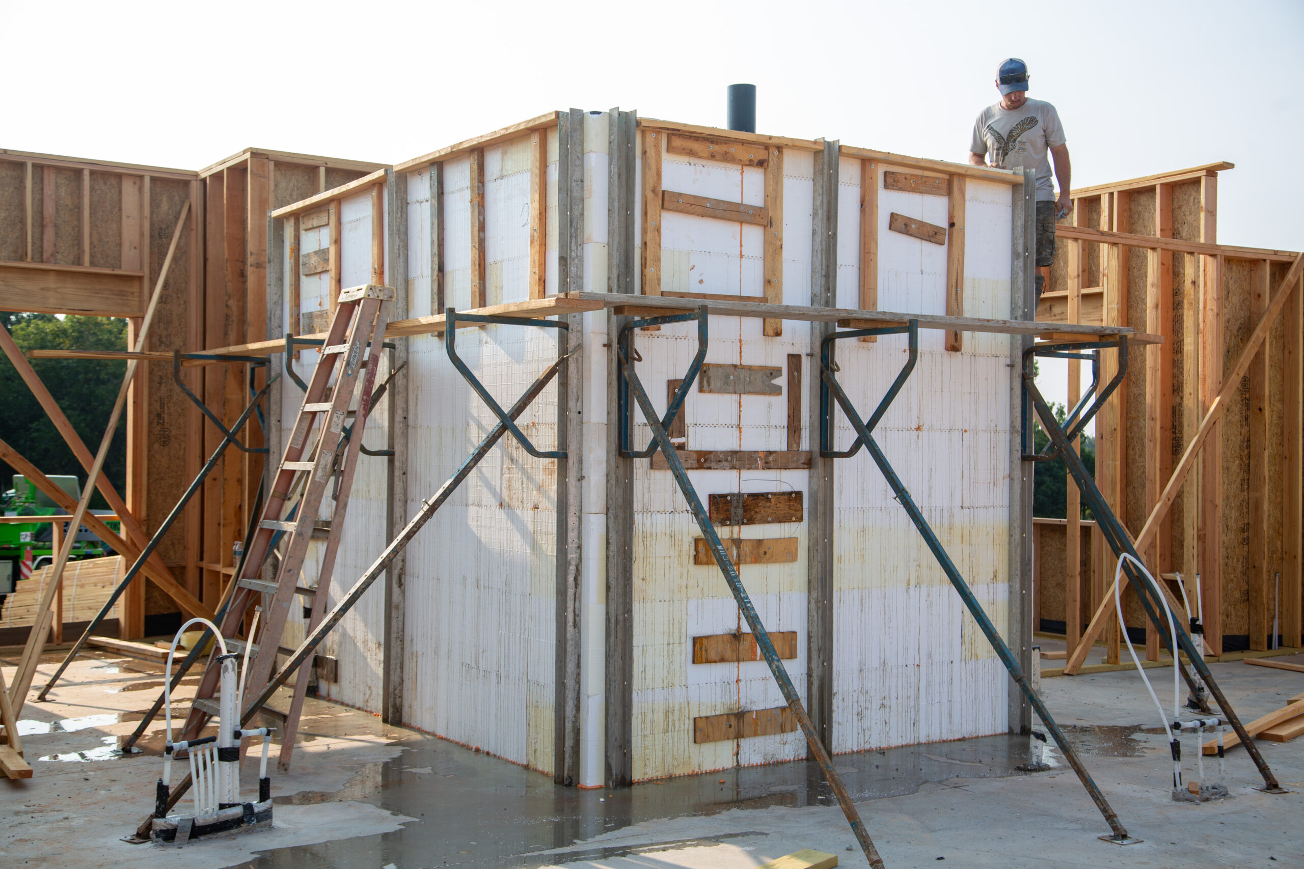
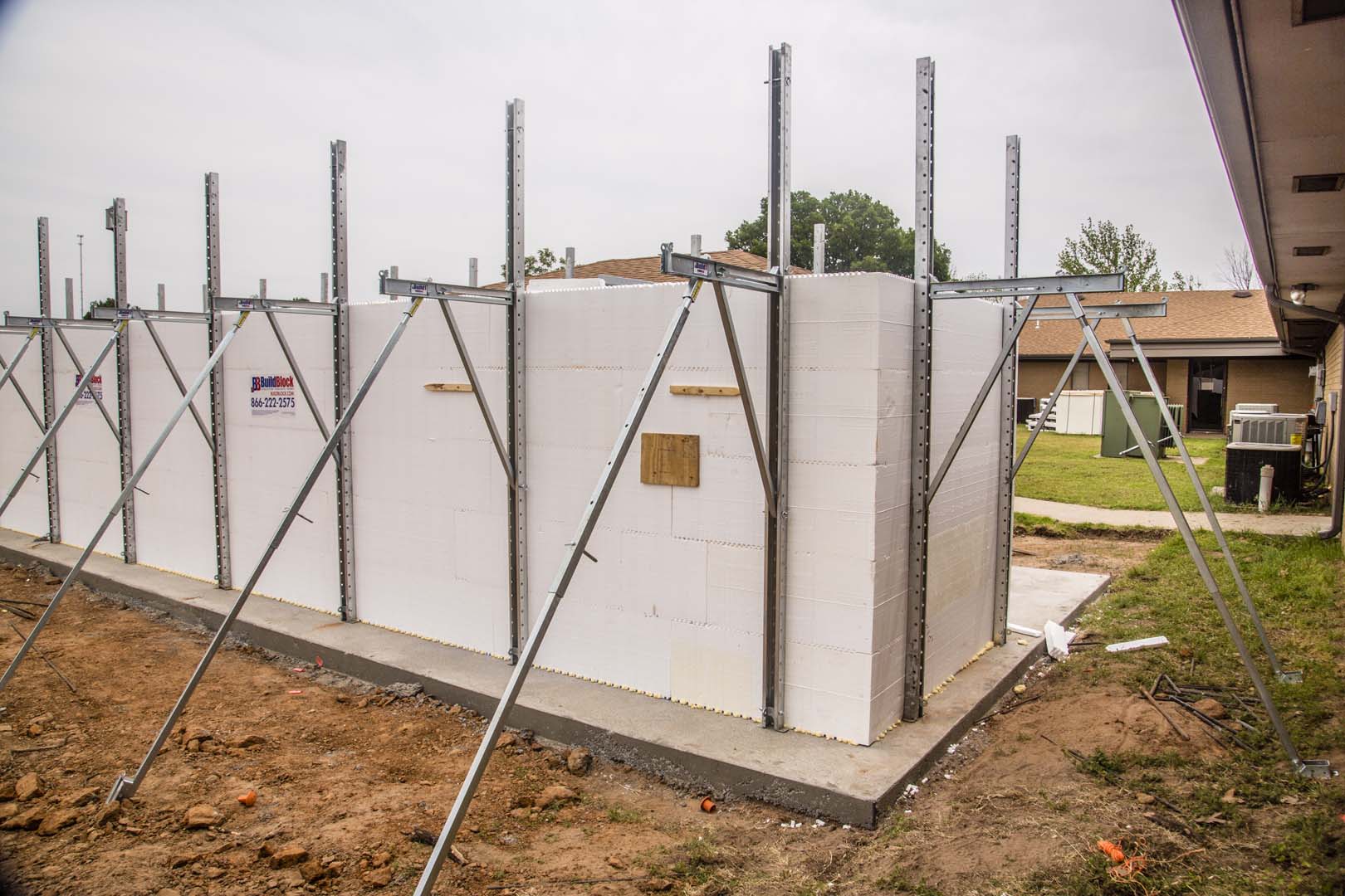
Walls braced and ready for concrete.
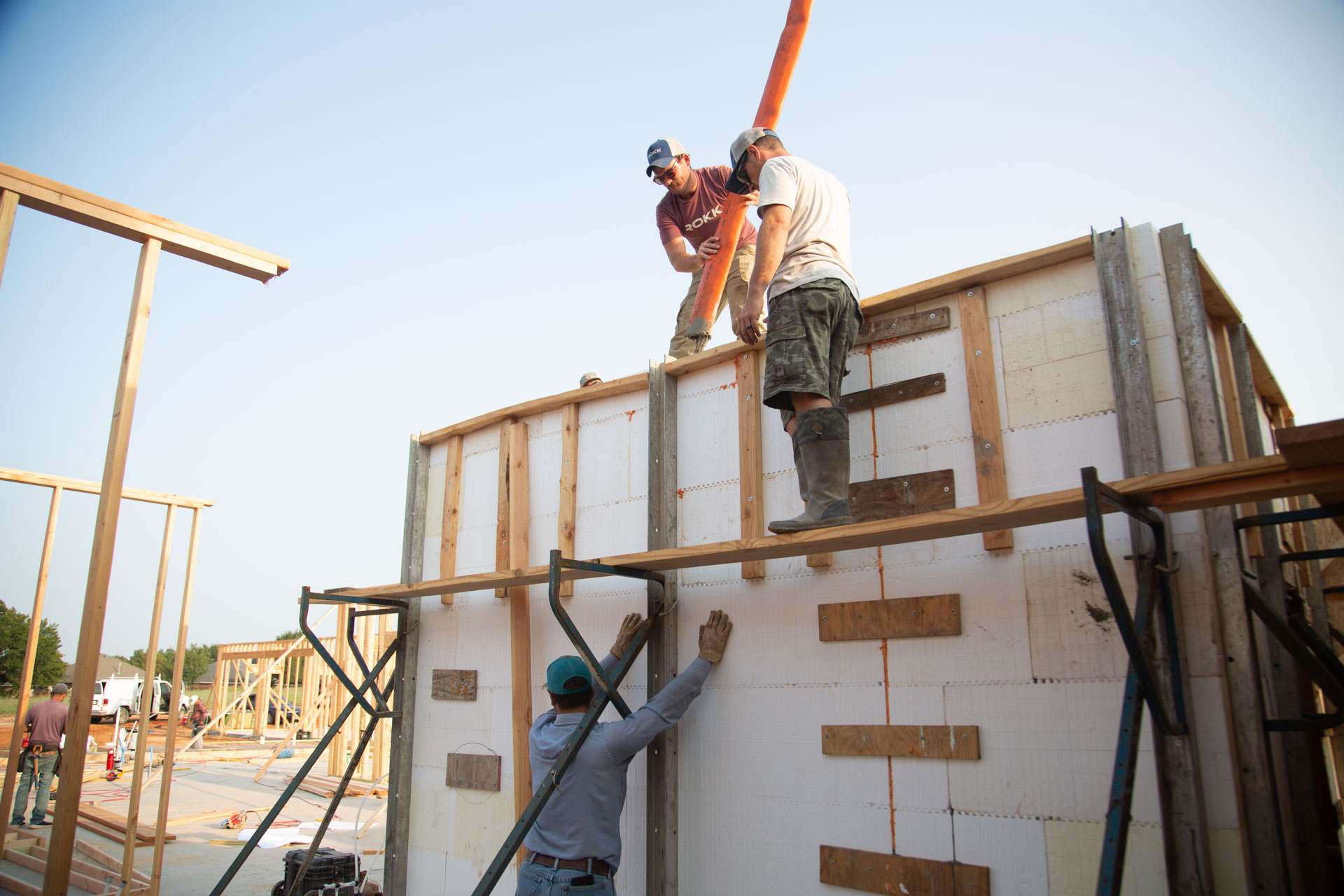
Pouring concrete into an ICF wall.
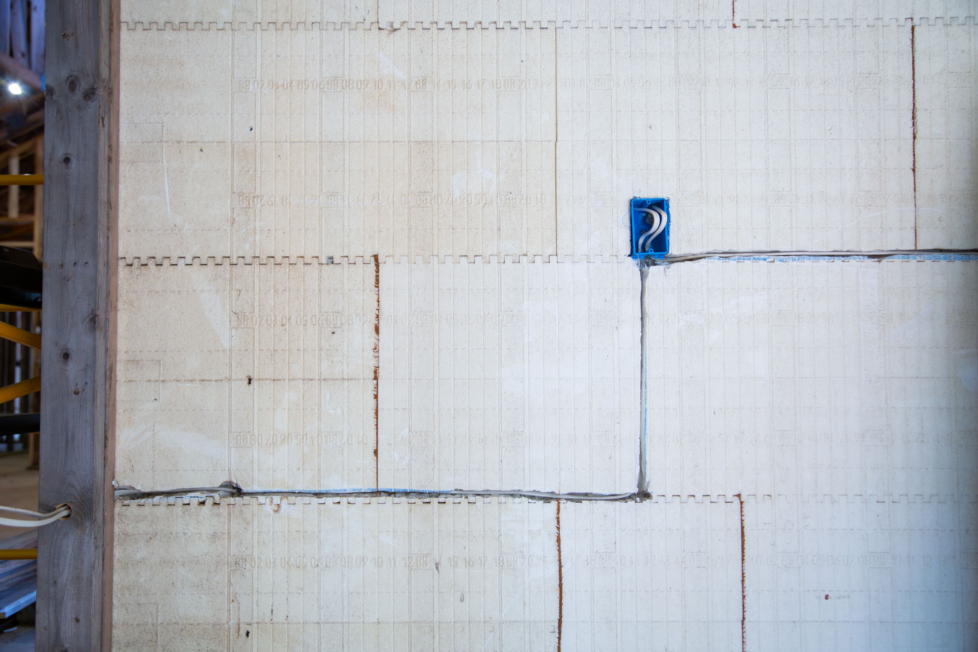
Electrical box and chases cut directly into an ICF wall.
Fully finished ICF safe room that doubles as a closet.
Cost Ranges
For an 8-by-8 interior safe room built into a new home in 2026, plan on around $10,000 -$15,000 all-in, depending heavily on the door you choose and the lid system. Here is how that typically breaks down:
The forms run $1,500 to $2,500. Concrete is $700 to $1,100. Rebar is $300 to $600. The door — your biggest single decision — is $1,000 to $2,000 if non-rated or $3,000 to $7,000 if FEMA-tested. Labor adds $3,000 to $6,000. Ventilation, electrical, and mechanical rough-ins add $800 to $1,800. Drywall and finishes add another $600 to $1,500.
If you are adding a safe room to an existing home rather than building one into a new house, costs typically run 30 to 50 percent higher because of demo, access, and the inability to share the foundation pour with the main structure. Safe rooms can always be added as an addition to an existing home instead of a retrofit.
FEMA’s Hazard Mitigation Grant Program reimburses safe room construction in many tornado-prone states — often 50 to 75 percent of the cost up to a cap. Check with your state emergency management agency before you build. Some insurance carriers also offer premium discounts for documented, FEMA-compliant safe rooms.
Questions to Ask Your Builder
A few questions will tell you quickly whether your builder has actually built ICF safe rooms before:
Does my safe room fall within Section 8.0 of the BuildBlock Engineering Manual, or do I need site-specific engineering?
What size rebar are you using, and at what spacing?
What door are you specifying, and is it ICC 500 tested as a labeled assembly?
Is the lid a poured slab or BuildDeck? How many air vents, where, and what type?
Will the room have its own electrical circuit with battery backup?
A confident answer to each of those questions is the sign you are working with the right builder.
Summary
BuildBlock ICF Safe Room
A BuildBlock safe room is not exotic construction. The same forms, the same concrete, and the same techniques your builder is already using on the rest of your home — applied to a small, fully reinforced concrete room with a tested door and proper ventilation. Correct execution of the engineered design, reinforcement, door, and ventilation produces a room that meets its protective standard. The details matter.
Discuss the design with your builder, review FEMA P-320, and confirm the door specification before construction.
BuildBlock Safe Room Construction: Builder and Installer Guide
This guide is intended for the contractor or installer building a residential safe room using BuildBlock Insulating Concrete Forms. It supplements — and in no place replaces — Section 8.0 of the BuildBlock Engineering Manual, the BuildBlock Technical Installation Manual, and the project engineer of record.
A safe room is reinforced concrete construction with no margin for sloppy work. The forms, concrete, and reinforcement schedule are not unusual; the discipline of the build is what produces a room that performs.
Residential ICF safe room built inside of a wood framed home.
ICF safe room being built inside of a wood framed home.
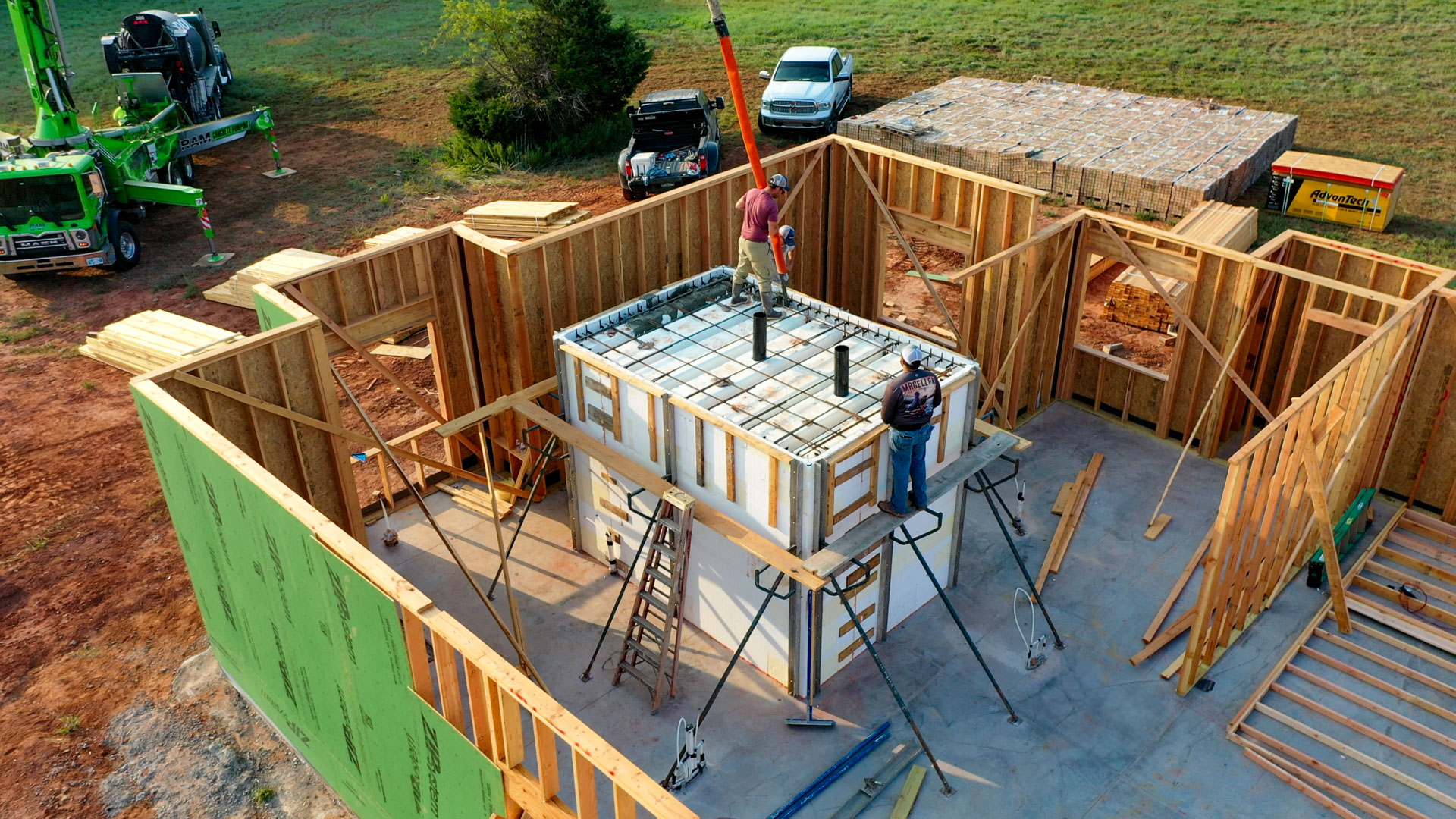
Installers monopouring residential ICF safe room walls and lid.
Installer pouring concrete for a residential ICF safe room.
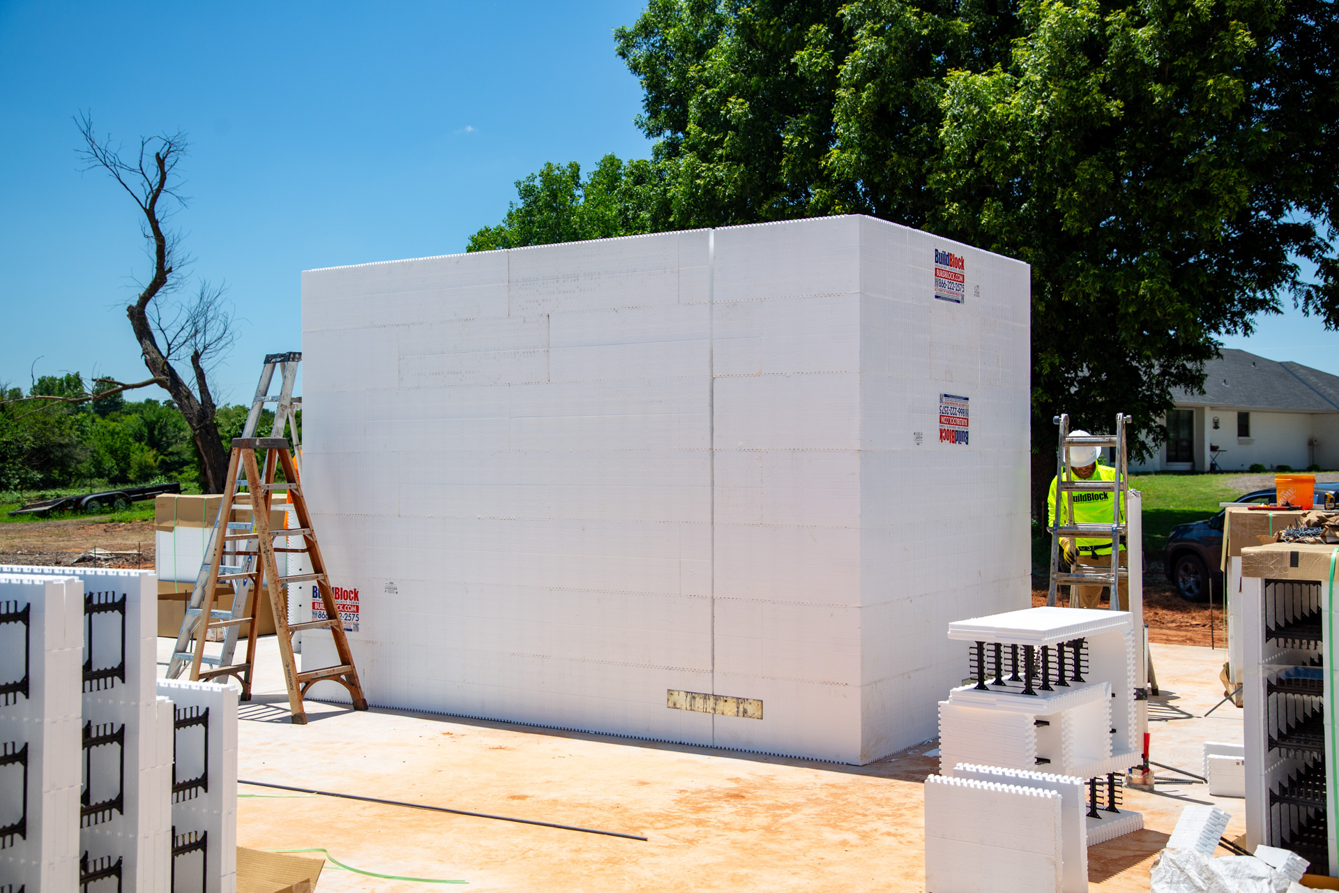
Stacking walls for an ICF safe room.
ICF safe room walls stacked to full height.
1.0 Pre-Engineered Design vs. Site-Specific Engineering
BuildBlock Safe Room Detail Sheet
PRE-ENGINEERED. Section 8.0 of the BuildBlock Engineering Manual provides prescriptive reinforcement schedules for safe room walls (Table 8.1) and BuildDeck lids (Table 8.2), along with ventilation sizing (Section 8.3) and connection details (Figures 8.1–8.4). Within the applicability envelope defined in Table 1.1 — design wind speed up to 250 mph 3-second gust, ground snow up to 70 psf, two stories plus basement, max 12 ft foundation wall height, max 20 ft unsupported wall height — the safe room can be built directly from the published tables without site-specific engineering.
SITE-SPECIFIC ENGINEERING. Required for any project outside the Table 1.1 envelope: coastal hurricane storm-surge zones, high seismic regions, taller-than-standard walls, atypical openings, or commercial occupancies. Commercial projects always require site-specific engineering. When in doubt, route the project through a qualified structural engineer.
FEMA AND ICC 500. The structural performance criteria referenced in FEMA P-361 and ICC 500 — 250 mph 3-second gust for tornado shelters, 15-lb 2×4 missile at 100 mph, occupant ventilation and density — are external standards that govern the safe room as an assembly. BuildBlock walls, BuildDeck lids, and the rebar schedules in Section 8.0 produce the structural envelope. The tested door assembly and the ventilation hardware are the two assembly components that carry their own ICC 500 test reports. Build the assembly correctly and label it correctly; do not overstate what the wall alone certifies.
2.0 Site Preparation
Strip topsoil and organic material. Compact subgrade to 95% standard Proctor density minimum. Verify bearing capacity matches the assumption in the engineered design — typically 2,000 psf minimum on undisturbed soil or engineered fill.
Stake the safe room footprint. Square the corners using the 3-4-5 method or a transit. Confirm the safe room layout is plumb and square with the rest of the foundation before the footing is poured.
Note: A safe room poured monolithically with the rest of the foundation cures and ties as one continuous reinforced concrete structure. Whenever practical, schedule the safe room footings as part of the main foundation pour.
3.0 Footing and Foundation
FOOTING SIZING. A typical interior safe room bears on a 16″ wide × 8″ deep continuous footing with 2-#4 longitudinal bars top and bottom. Verify against the engineered design for your project.
LEVEL TOLERANCES MATTER. Pour the footing within 1/4″ of level over the length of any wall. Deviations telegraph up through every course of the form lift.
FOOTING-TO-WALL CONNECTION DOWELS. This is the single most critical detail in the entire safe room. Set vertical rebar dowels into the wet footing concrete at the same spacing as the wall verticals specified in Section 8.0 Table 8.1 — for the most common configuration (6″ core, up to 10 ft wall), that is #4 at 12″ on center. Embed each dowel a minimum of 6″ into the footing and project a minimum of 24″ above the top of the footing (or whatever the engineered lap length requires for your bar size and concrete strength).
DOWEL PLACEMENT. At a 6“, 90° corner, set the first dowel 5-1/2” from the inside corner on one face and 8-1/2″ on the other. Continue the remaining dowels at 6“/12”/18“/24” working away from the corner, then transition to standard 12″ o.c. for the run of wall. Reference Figure 9.5 in the Engineering Manual for the standard footing connection.
DO NOT FIELD-BEND. Place dowels precisely the first time. Field bending to fit a form web induces residual stress in the bar and can compromise the connection. If a dowel is in the wrong location, cut it flush and epoxy-set a new one.
Snap a chalk line on the cured footing at the inside face of the wall. That line is the reference for the entire stack.
Prepare the site for ICF safe room installation.
4.0 Stacking the Forms
Stack BuildBlock forms dry, in a running bond, with seams offset a minimum of 6″ between courses. Start at a corner with a corner form and work outward.
SQUARE AND PLUMB EVERY COURSE. Verify with a 4 ft level on each wall. Small errors at course 1 become large errors at course 6.
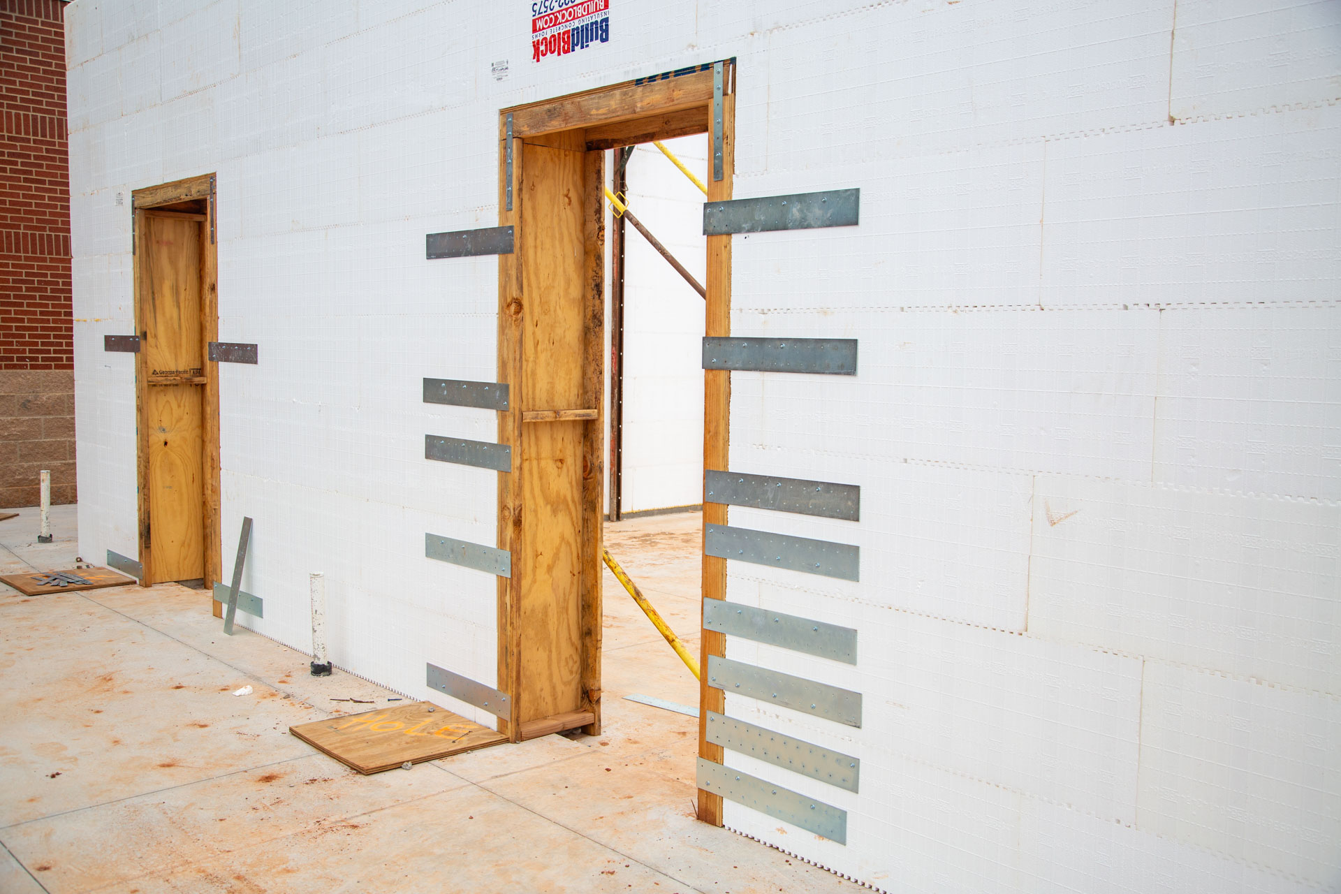
DOOR FRAME. Set the door frame in the wall and finish stacking. Reinforce on either side of the door as specified and construct the lintel as specified.
ICF installers stacking block to form exterior walls.
5.0 Rebar Reinforcement
Reinforcement schedule is per Section 8.0 Table 8.1, indexed by core width and wall height. For the most common residential configurations:
6″ core, wall up to 10 ft: Vertical #4 @ 12″ o.c.; Horizontal #4 @ 16″ o.c.
Corner bars bent at 90° with minimum 24″ lap each direction. Jamb reinforcement at door openings: 2-#5 vertical bars full height each side of the opening. Lintel above the opening: #5 minimum, extending 24″ past each jamb (verify against Section 7.0 lintel tables for your specific opening width and load).
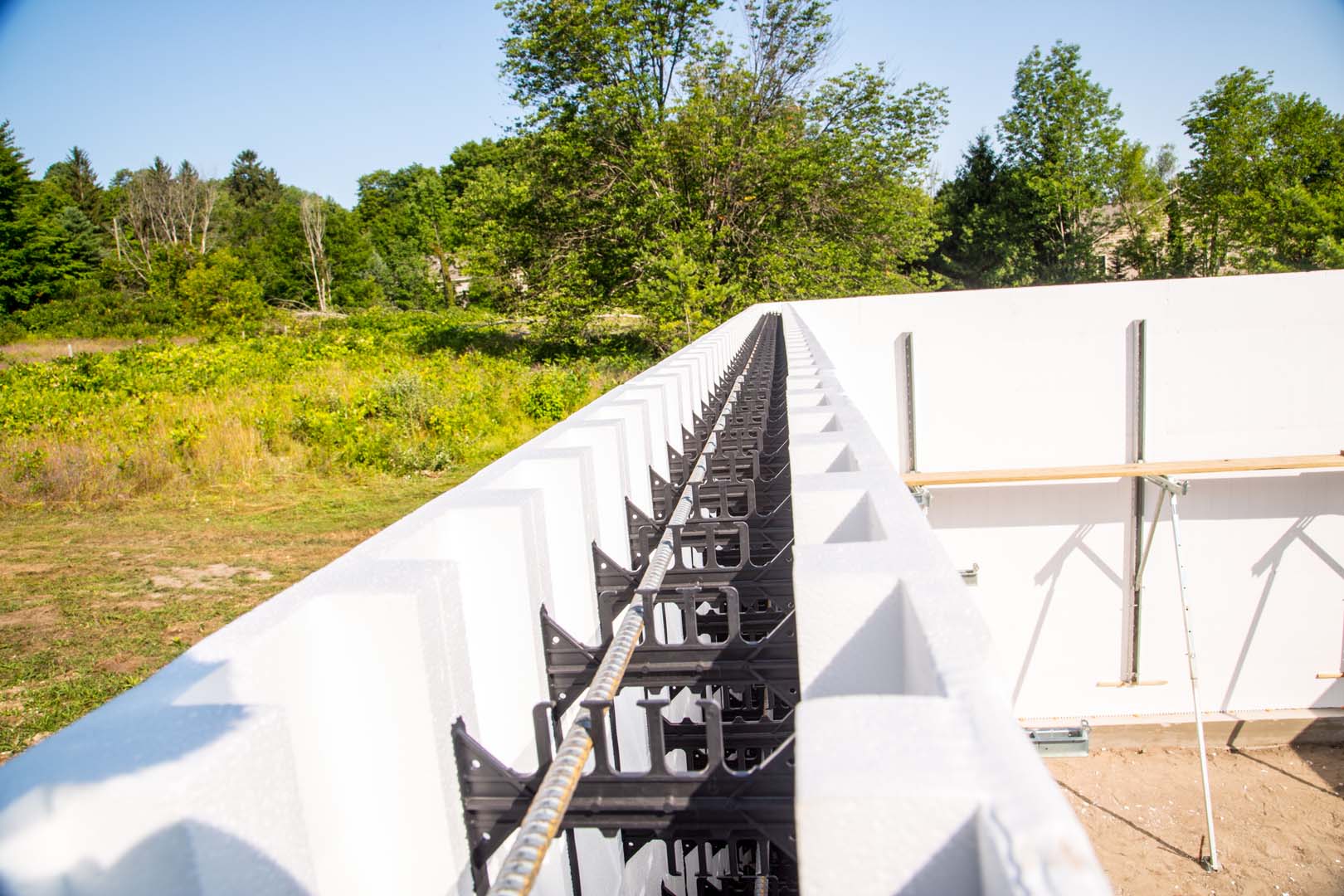
CENTER OF CORE. All rebar rests in the integral plastic web chairs of the BuildBlock form, positioned in the center of the concrete core. Concrete cover is what protects the steel. Do not let bar lean against either foam face. Horizonal rebar should alternate either side of center to create a chase for the vertical rebar in the center of the core. Rebar should be secure at the top of the wall.
LAP SPLICES. Vertical wall bars lap to footing dowels a minimum of 24″ (or the lap specified in the engineered design — longer for #5 and larger bars). Top-of-wall verticals bent to tie into the lid/cap reinforcement grid. Lap can originate from either the lid steel or wall steel or as a separate bar lapped appropriately.
Steel reinforcement placed horizontally in ICF web fingers.
Steel corner rebar in web fingers.
Rebar dowels for ICF wall connection.
6.0 Safe Room Doors
The door is the assembly component that carries its own ICC 500 / FEMA 361 test label. The wall provides the structural envelope; the door provides the certified opening.
RATED ASSEMBLIES. A tested, labeled door assembly — door, frame, hinges, anchorage, and latching hardware — is engineered and tested together. Common manufacturers include Rhino, USTC, Survive-a-Storm, Texas Safe Room Doors, and Storm Shield. Expect $3,000 to $7,000 installed for a labeled assembly.
NON-RATED HEAVY STEEL DOORS. Heavy-gauge steel doors in steel frames can be specified outside the tested-assembly market. They may perform similarly under stress but they carry no test report and no label — think of it as the difference between a name-brand and a generic product. Both can be appropriate; only one can be advertised as FEMA-compliant. Be honest with the customer about which one they are buying.
ANCHORAGE. Anchor the frame exactly per the door assembly’s published test report — anchor type, size, and spacing are part of the tested assembly and cannot be substituted without voiding the label. BuildBlock safe room frames are cast in place: set the frame plumb, square, and braced, and pour the concrete around the frame’s integral anchor straps, tabs, or cast-in bolts per the report. Only if the specified assembly instead calls for post-pour anchorage should you drill the report’s pattern (typically ½” wedge or adhesive anchors at hinge and strike locations). Do not substitute powder-actuated fasteners or sleeve anchors unless the report explicitly approves them.
Disaster rated steel door frames for safe rooms.
7.0 Bracing
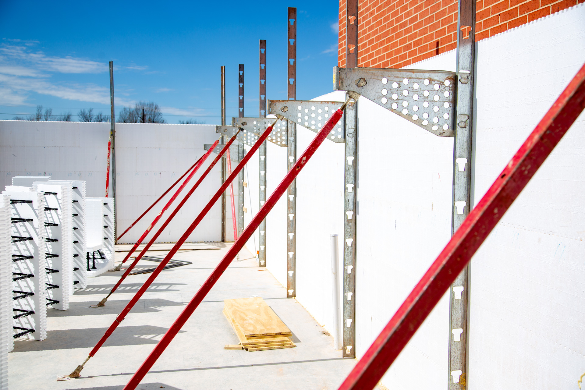
Set ICF bracing at 6 ft o.c. on every wall. Brace short walls. Brace walls with door openings. Bracing doubles as a scaffold platform and as the plumb adjustment for the pour. Re-check plumb immediately before the pour and again after the first 4-foot lift. ICF walls may compress up to 1/16″ per course during the pour — adjust the bracing as you go.
Do not remove vertical bracing for at least 48–96 hours after the pour, or longer in cold weather.
BuildBrace attached to an ICF safe room wall.
8.0 Pre-Pour Inspection
Run through this list before the pump truck arrives:
Rebar size, spacing, lap lengths, and dowel projections verified against Section 8.0 Table 8.1.
Concrete cover verified — all bar centered in core, none touching foam face.
Door plumb, square, dimension verified, braced.
Electrical conduit, boxes, and venting penetrations installed, capped, and secured.
Top-of-wall dammed or formed to accept lid pour and to transfer vertical bar projection.
All bracing tensioned and walls plumb.
Walls straight, plumb, square, and level.
Photographs of every wall face — these are the as-built record.
Labor ready to internally vibrate and consolidate concrete each lift, and materials staged and on-hand in case of any problems during the pour.
Get the engineer or building official sign-off if required by local jurisdiction. Do not pour without it.
Horizontal and vertical rebar in high density plastic web fingers.
Doorframe bucked with wood and strapped for the concrete pour.
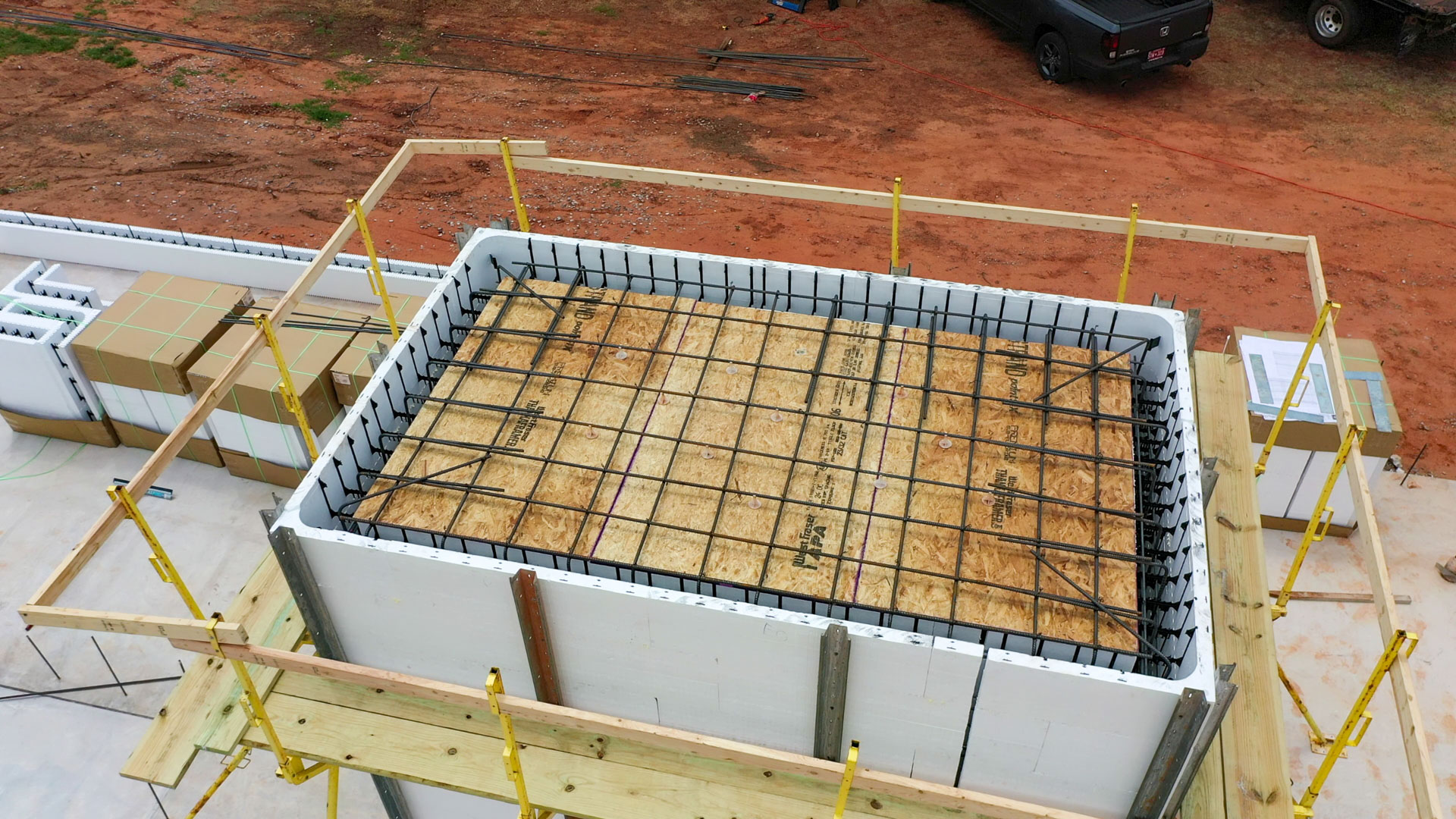
ICF safe room walls stacked and lid reinforcement in place.
ICF storm shelter walls braced and ready for the concrete pour.
Electrical box and chases cut directly into an ICF wall.
9.0 Concrete Placement and Consolidation
MIX DESIGN. 3,000–4,000 psi compressive strength, 3/8″ max aggregate, 6–6.5″ slump (or 5–7″ with a mid-range water reducer), air entrainment per climate. Do not add water at the truck.
PUMP AND PLACE. Begin pouring 4 to 5 ft from a corner. Direct the concrete flow toward the corner, then move along the wall. Never pour directly down a corner — it stacks pressure at the joint and invites blowouts.
LIFTS. Place in 4 ft lifts. Walk the perimeter on each lift.
CONSOLIDATION. Use a pencil vibrator with a 3/4″ to 1″ head. Insert at 24″ to 36″ intervals for 5 to 10 seconds per insertion. Over-vibration is as damaging as under-vibration — it segregates aggregate, raises hydrostatic pressure, and triggers blowouts.
Pouring a commerical ICF storm shelter wall while avoiding pouring directly into the corner.
10.0 Pour Problems and Fixes
BLOWOUT. Stop the pour. Brace the area with plywood and 2×4 strongbacks. Screw or strap the patch in place. Resume placement once the patch is secure. Most BuildBlock blowouts can be repaired in 10 minutes if caught early.
FORM DRIFT. Correct with bracing and alignment while the concrete is plastic. Re-check plumb every 15 minutes during the pour maintaining plumb. A 1/2″ drift is correctable; a 2″ drift after initial set is not.
HONEYCOMBING. Vibrate carefully around door openings and lintels where rebar density is highest. Vibrate properly the first time and prevent honeycombing or voids.
REBAR SHIFT. Verify chairs, ties, and dowel placement before the pour, not during it. Once concrete starts flowing it is too late to reposition.
Vibrating concrete inside ICF walls
11.0 Lid / Roof Design Options
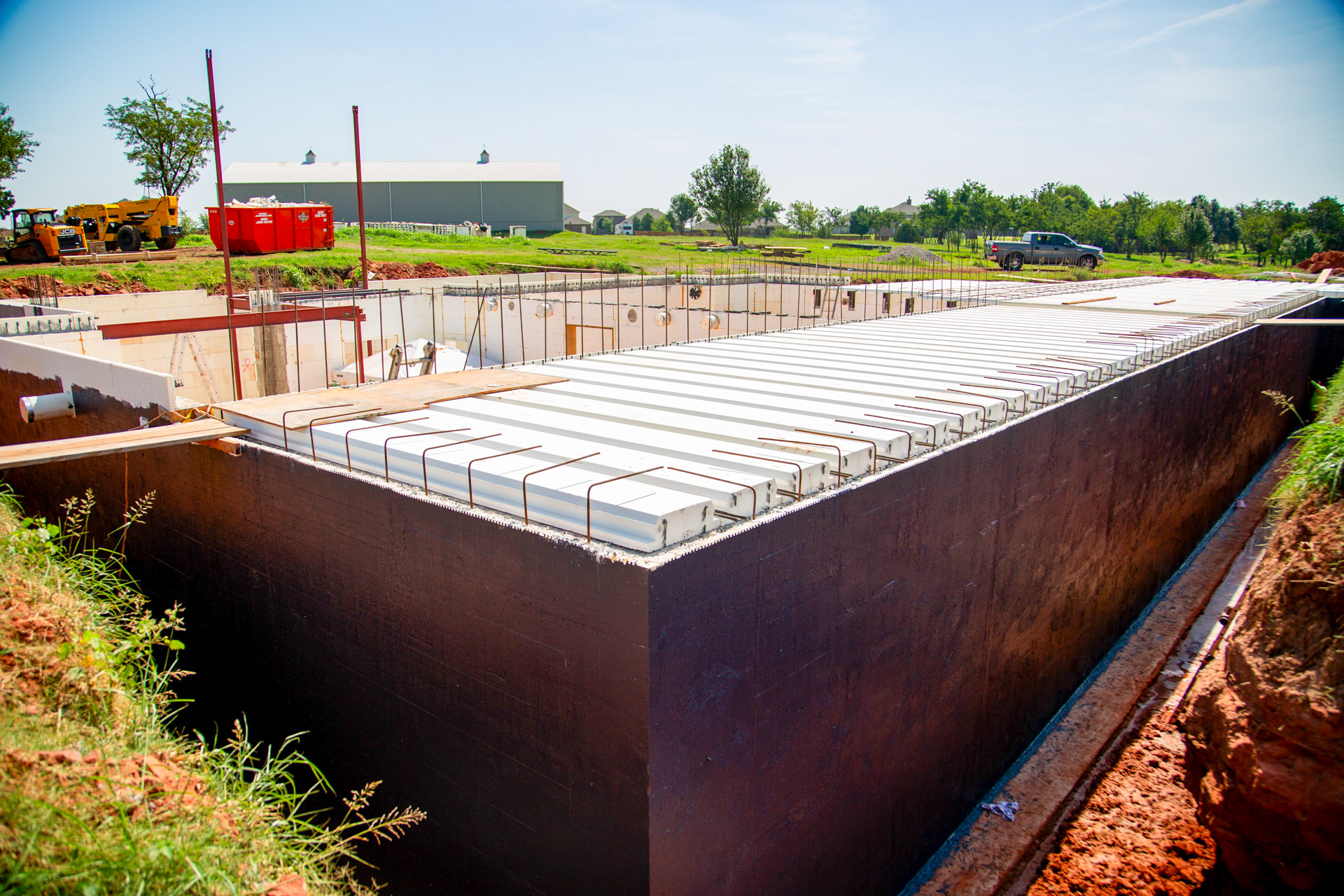
BUILDDECK (PREFERRED). Section 8.0 Table 8.2 specifies BuildDeck (BD800, BD1000, BD1200) as the engineered lid system for BuildBlock safe rooms. BuildDeck panels span between bearing walls, accept the reinforcement schedule in Table 8.2 (e.g., 2-#5 bottom / 1-#5 top for BD800 at 12 ft span), and pour as a one-way ribbed slab integrated with the wall. BuildDeck eliminates shoring, integrates continuous insulation into the lid, and produces a finished ceiling assembly ready for drywall. Place shear stirrups in the BuildDeck ribs per Table 8.2 (End “D” distance) and Figure 8.4.
POURED SLAB ON PLYWOOD FORMS. The traditional approach: 3/4″ plywood deck on 2×10 or LVL joists at 16″ o.c., shored to the floor below at 4 ft o.c. Pour a 6“–8” reinforced slab with #4 bar at 12″ o.c. each way, top and bottom mats. Strip forms at 7 days minimum, 14 days for full design load.
LITEDECK AND QUAD-DECK. Alternative ICF decking systems. Verify with the engineer before substituting — Section 8.0 prescriptive tables are written for BuildDeck.
CONTINUITY. Wall verticals extend up and bend into the lid reinforcement to produce a continuous reinforced concrete box. This is non-negotiable. A lid that is not tied to the walls is a separate structure that will fail in shear at the joint. Connections can be from bar bent into the cap, from the cap into the wall, or appropriately lapped rebar.
BuildDeck ICF Home
ICF decking system installed on top of BuildBlock walls.
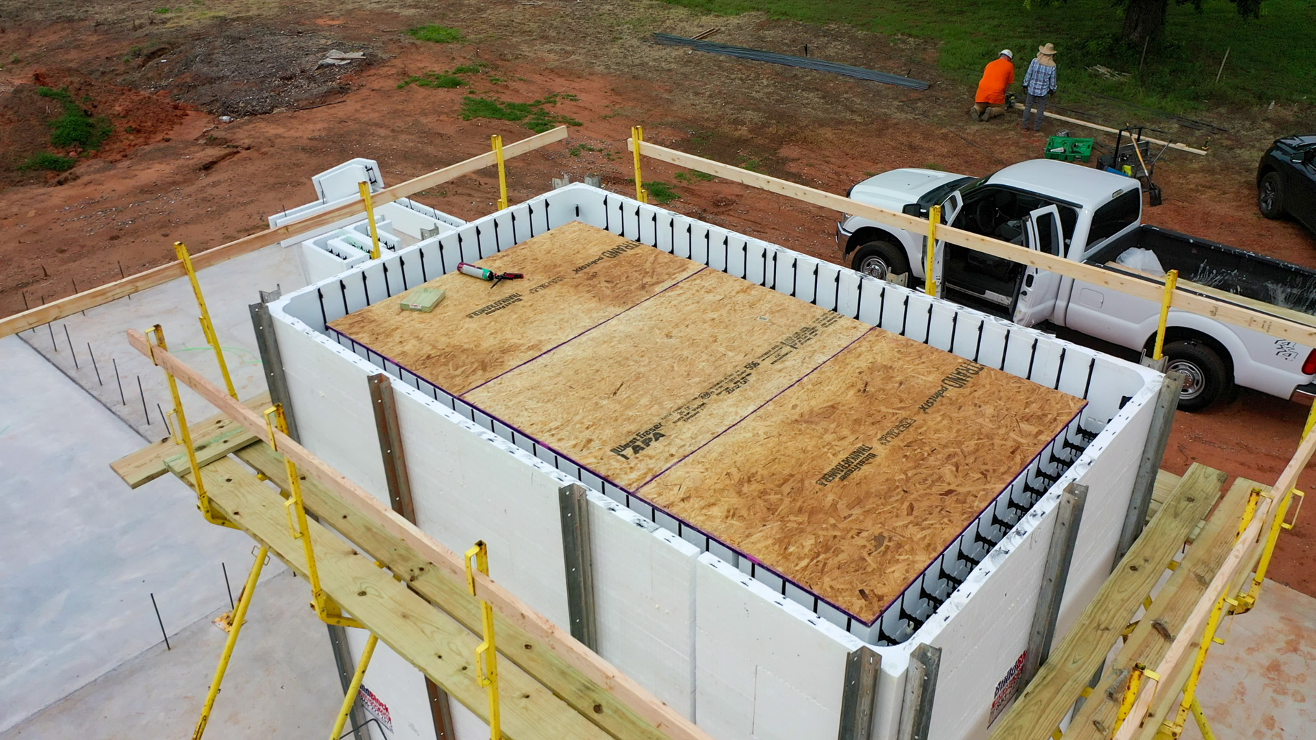
Plywood in place for ICF safe room poured slab concrete roof.
12.0 Ventilation
Section 8.0 of the Engineering Manual specifies Atmospheric Pressure Change (APC) venting at 1 ft² per 1,000 ft³ for tornado shelters and combination shelters, using 2″ diameter pipe with elbows installed facing down.
Per-occupant ventilation area: 2 in² tornado / 4 in² hurricane for residential occupancies. Occupant density: 3 sq ft per occupant for tornado, 7 sq ft for hurricane in 1- and 2-family residential applications.
Vent assemblies must resist missile penetration. Use impact-rated louvers, missile-rated or baffled per BuildBlock Figure 8.3. Do not use ordinary HVAC grilles — they will not pass the missile test.
If the safe room is also a closet or bathroom served by the main HVAC, install a damper or shut-off so the safe room is not vented to the outside through the rest of the house during a storm.
Blockout in a residential ICF safe room lid for the installation of a vent.
13.0 Electrical
Rough-in sleeves for electrical or any plumbing before the pour. Schedule 40 PVC or EMT conduit as needed. After the pour and initial cure, strip foam with a chainsaw, router or hot knife back to the concrete face and secure wiring, plumbing or other mechanicals. Only remove enough foam to fit the wire, conduit or plumbing. Secure with spray foam adhesive every 12-18” and ensure it is placed against the concrete to provide the appropriate depth to meet code requirements.
Minimum electrical fit-out: – Ceiling-mounted LED light fixture – Two duplex receptacles – One generator- or battery-backed circuit – Hard-wired smoke and CO detector – Outlet for NOAA weather radio or charger
Run safe room circuits on a dedicated breaker. Consider a UPS or battery backup as redundancy.
Use a chainsaw to cut electrical chases into an ICF wall.
14.0 Interior Finishes
Drywall (1/2″ or 5/8“) screws directly to the embedded plastic webs at 6” o.c. Tape, mud, prime, and paint conventionally. Closet rods and shelving fasten to the plastic webs for full design load or remove foam and secure wood blocking to the concrete to provide attachment surface.
For the lid, drywall screws into BuildDeck c-channel steel if used or into furring strips fastened to a poured slab. Recessed lighting, crown molding, and acoustic treatments install conventionally.
Drywall installed in a commercial storm shelter which doubles as a bathroom. This storm shelter features plumbing, electrical, and a sprinkler system.
15.0 Commissioning
Before turnover: – Verify door swings freely, latches positively, and seals to the frame at all four edges. – Test all electrical circuits, smoke/CO detector, and battery backup. – Confirm vent assemblies are clear and louvers operate. – Provide the owner with the door assembly test report, the engineered design or Section 8.0 reference, and a one-page summary of safe room use (occupancy, ventilation, what to bring during a storm).
FEMA P-361, Safe Rooms for Tornadoes and Hurricanes (Fourth Edition)
FEMA P-320, Taking Shelter from the Storm
ICC 500, Standard for the Design and Construction of Storm Shelters
BuildBlock Safe Room Planning and Construction Checklist
For contractors and installers building residential safe rooms with BuildBlock Insulating Concrete Forms. Use alongside Section 8.0 of the BuildBlock Engineering Manual and the project engineer of record.
Stack forms dry in running bond. Offset seams minimum 6″.
Verify plumb and square at every course with a 4 ft level.
Glue, tie or strap any seam likely to shift during pour.
Form door rough opening and place door frame in place. Safe room door frames are cast in place, versus standard doors that are bucked and doors installed later.
Verify RO dimensions match door manufacturer cut sheet.
Strap across door and brace bottom of frame to ensure frame does not move during the pour. You can also cut plywood or other material to overlap the door and secure to webs on either side of the door to ensure it does not move or shift.
Place horizontal rebar at every course per Table 8.1. Alternate either side of center to create a chase to keep verticals in place centered in the core.
Order or bend corner bars 90° with 24″ minimum lap each direction.
Set jamb reinforcement: 2-#5 verticals each side of door opening.
Set lintel bar above door opening per Section 7.0 lintel tables.
Verify all bar centered in core. Use web chairs in BuildBlock forms.
Top-of-wall verticals project above final course for lid lap.
Drop vertical rebar into cores per Section 8.0 Table 8.1.
Lap verticals to footing dowels minimum 24″. Dowels from the footing should be 24” above the top of the footing.
Set BuildDeck panels per manufacturer instructions and Table 8.2.
Place reinforcement per Table 8.2 (e.g., BD800: 2-#5 bottom, 1-#5 top).
Place shear stirrups per Table 8.2 (End “D” distance) and Figure 8.4.
Tie wall verticals into lid reinforcement for continuity.
Shore appropriately per the BuildDeck Installation Manual. For short spans, shore via 4×4 or adjustable jack shoring posts. If possible leave in place for 14 days for full cure. If necessary, and spans are short vertical shoring can be removed after 7-10 days.
Pour, vibrate, and cure per BuildDeck installation manual.
Poured slab on plywood:
Set 3/4″ plywood deck on 2×10 or LVL joists at 16″ o.c.
Shore to floor below at 4 ft o.c.
Place top and bottom rebar mats per engineered design.
Tie wall verticals into slab reinforcement.
Pour, vibrate, and cure.
Strip forms minimum 7 days, 14 days for full load.
Set door frame in opening before pour. Verify plumb and square before and after pour.
Anchor the frame exactly per the door assembly’s published test report — the anchor type, size, and spacing are part of the tested assembly and cannot be substituted without voiding the label. Safe room door frames are cast in place: set the frame plumb, square, and brace, and pour the concrete around the frame’s integral anchor straps, tabs, or cast-in bolts per the report. Only if the specified assembly instead calls for post-pour anchorage should you drill the report’s pattern (typically ½” wedge or adhesive anchors at hinge and strike locations).
Do not substitute powder-actuated fasteners or sleeve anchors unless the report explicitly approves them.
Confirm mix design at the truck. Do not add water.
Begin pouring 4 to 5 ft from a corner.
Set a small amount of concrete on either side of the door frame to balance the pressure during the pour.
Direct flow toward the corner, then along the wall.
Place in 4 ft lifts. Working your way around the walls until you reach the top. Vibrate each new lift into the previous one.
Pour the cap consolidating carefully and screen level and smooth.
Consolidate with pencil vibrator (3/4″ to 1″ head).
Insert vibrator at 24″ to 36″ intervals, 5 to 10 seconds each.
Re-check plumb every 15 minutes during pour. Alternatively use a string line to ensure wall stays level and plumb.
Adjust bracing to correct any drift while concrete is plastic.
Never pour directly down a corner. Never over-vibrate — it segregates aggregate and triggers blowouts. Be careful over-vibrating too close to windows and doors.
Blowout: stop, brace with plywood and 2×4 strongbacks, screw in place, resume.
Form drift: correct with turnbuckle braces while concrete is moveable.
Honeycombing: vibrate carefully around dense rebar zones.
Rebar shift: too late to fix during pour — verify before the pour. Ensure proper placement and rebar is secure at the top of the wall and the wall to lid/deck connection.
Hang drywall directly to embedded plastic webs at 6″ o.c.
Tape, mud, prime, and paint conventionally.
Install flooring and trim.
Mount any shelving or closet rods directly into plastic webs. You can also strip foam and attach wood blocks to concrete directly to create mounting points before drywall installation.